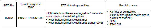
Nissan Juke Service and Repair Manual : B261A push-button ignition switch
DTC Logic
DTC DETECTION LOGIC
NOTE
:
• If DTC B261A is displayed with DTC U1000, first perform the trouble diagnosis
for DTC U1000. Refer to
BCS-83, "DTC Logic".
• If DTC B261A is displayed with DTC U1010, first perform the trouble diagnosis for DTC U1010. Refer to BCS-84, "DTC Logic".
DTC CONFIRMATION PROCEDURE
1.PERFORM DTC CONFIRMATION PROCEDURE
1. Press the push-button ignition switch under the following conditions, and wait for 1 second or more.
CVT models
- Selector lever is in the P or N position
- Do not depress brake pedal
M/T models
- Do not depress clutch pedal
2. Check “Self-diagnosis result” of BCM with CONSULT-III.
Is DTC detected? YES >> Go to PCS-101, "Diagnosis Procedure".
NO >> INSPECTION END
Diagnosis Procedure
1.CHECK IGNITION SWITCH OUTPUT SIGNAL (PUSH-BUTTON IGNITION SWITCH)
1. Disconnect push-button ignition switch connector and IPDM E/R connector.
2. Check voltage between push-button ignition switch harness connector and ground.
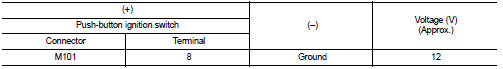
Is the inspection result normal? YES >> GO TO 3.
NO >> GO TO 2.
2.CHECK PUSH-BUTTON IGNITION SWITCH CIRCUIT (BCM)
1. Disconnect BCM connector.
2. Check continuity between BCM harness connector and push-button ignition switch harness connector.
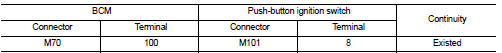
3. Check continuity between push-button ignition switch harness connector and ground.
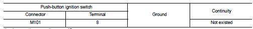
Is the inspection result normal? YES >> Replace BCM. Refer to BCS-93, "Removal and Installation".
NO >> Repair or replace harness.
3.CHECK IGNITION SWITCH OUTPUT SIGNAL (IPDM E/R)
Check voltage between IPDM E/R harness connector and ground.
Is the inspection result normal? YES >> Replace IPDM E/R.
NO >> GO TO 4.
4.CHECK PUSH-BUTTON IGNITION SWITCH CIRCUIT (IPDM E/R)
1. Disconnect BCM connector.
2. Check continuity between IPDM E/R harness connector and push-button ignition switch harness connector.
3. Check continuity between push-button ignition switch harness connector and ground.
Is the inspection result normal? YES >> GO TO 5.
NO >> Repair or replace harness.
5.CHECK INTERMITTENT INCIDENT
Refer to GI-42, "Intermittent Incident".
>> INSPECTION END
 B2618 BCM
DTC Logic
DTC DETECTION LOGIC
NOTE:
• If DTC B2618 is displayed with DTC U1000, first perform the trouble diagnosis
for DTC U1000. Refer to
BCS-83, "DTC Logic".
• If DTC B2618 is ...
 B26F1 ignition relay
DTC Logic
DTC DETECTION LOGIC
DTC CONFIRMATION PROCEDURE
1.PERFORM DTC CONFIRMATION PROCEDURE
1. Turn ignition switch ON under the following conditions, and wait for 2
seconds or more.
CVT ...
Other materials:
Range
The total driving distance your Nissan Leaf can cover on a single charge is dynamic. This range varies considerably based on a complex interplay of factors, including your current battery state of charge, prevailing weather conditions, ambient temperatures, specific usage patterns, the overall age o ...
Door does not lock/unlock with door lock and unlock
switch
All door
ALL DOOR : Description
All doors do not lock/unlock using door lock and unlock switch.
ALL DOOR : Diagnosis Procedure
1.CHECK DOOR LOCK AND UNLOCK SWITCH
Check door lock and unlock switch. Refer to the following.
• Driver side: Refer to DLK-391, "DRIVER SIDE : Component Funct ...
All-Wheel Drive (AWD) mode switch operations
AWD mode switch
The All-Wheel Drive (AWD) system is used to select the 2WD (Two-Wheel Drive),
AWD-V or AWD mode depending on the driving conditions.
The AWD mode indicator lights ( (green),
) are located in the instrument panel.
The AWD mode indicator lights (green)
illuminate when the ig ...
