Nissan Juke Service and Repair Manual : B26F1 ignition relay
DTC Logic
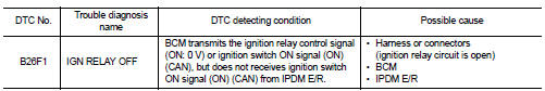
DTC DETECTION LOGIC
DTC CONFIRMATION PROCEDURE
1.PERFORM DTC CONFIRMATION PROCEDURE
1. Turn ignition switch ON under the following conditions, and wait for 2 seconds or more.
CVT models
- Selector lever is in the P or N position
- Do not depress brake pedal
M/T models
- Do not depress clutch pedal
2. Check “Self-diagnosis result” with CONSULT-III.
Is DTC detected? YES >> Go to PCS-103, "Diagnosis Procedure".
NO >> INSPECTION END
Diagnosis Procedure
1.CHECK IPDM E/R SELF-DIAGNOSTIC RESULT
1. Turn ignition switch ON.
2. Erase the DTC of IPDM E/R.
3. Turn ignition switch OFF.
4. Turn ignition switch ON and check the DTC again.
Is DTC detected? YES >> Repair or replace the malfunctioning part. Refer to PCS-25, "DTC Index".
NO >> GO TO 2.
2.CHECK IGNITION RELAY (IPDM E/R) CONTROL SIGNAL
Check voltage between BCM harness connector and ground.
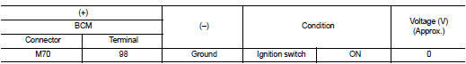
Is the inspection result normal? YES >> GO TO 3.
NO >> Replace BCM. Refer to BCS-93, "Removal and Installation".
3.CHECK IGNITION RELAY (IPDM E/R) CONTROL SIGNAL CIRCUIT
1. Turn ignition switch OFF.
2. Disconnect BCM and IPDM connectors.
3. Check continuity between BCM harness connector and IPDM E/R harness connector.

Is the inspection result normal? YES >> Replace IPDM E/R.
NO >> Repair or replace harness.
 B261A push-button ignition switch
DTC Logic
DTC DETECTION LOGIC
NOTE:
• If DTC B261A is displayed with DTC U1000, first perform the trouble diagnosis
for DTC U1000. Refer to
BCS-83, "DTC Logic".
• If DTC B261A is ...
 B26F2 ignition relay
DTC Logic
DTC DETECTION LOGIC
DTC CONFIRMATION PROCEDURE
1.PERFORM DTC CONFIRMATION PROCEDURE
1. Turn ignition switch ON under the following conditions, and wait for 2
seconds or more.
CVT ...
Other materials:
Intake valve timing control
Intake valve timing control : System Diagram
Intake valve timing control : System Description
INPUT/OUTPUT SIGNAL CHART
SYSTEM DESCRIPTION
This mechanism hydraulically controls cam phases continuously with the fixed
operating angle of the intakevalve.
The ECM receives signals such as ...
B terminal circuit
Description
“B” terminal circuit supplies power to charge the battery and to operate the
vehicle’s electrical system.
Diagnosis Procedure
1.CHECK “B” TERMINAL CONNECTION
1. Turn ignition switch OFF.
2. Check if “B” terminal is clean and tight.
Is the inspection result normal? ...
Security systems
To provide comprehensive protection, your Nissan Leaf is equipped with two distinct security systems designed to safeguard your vehicle:
Vehicle security system
NISSAN Vehicle Immobilizer System
The current operational status of these systems ...
