Nissan Juke Service and Repair Manual : B terminal circuit
Description
“B” terminal circuit supplies power to charge the battery and to operate the vehicle’s electrical system.
Diagnosis Procedure
1.CHECK “B” TERMINAL CONNECTION
1. Turn ignition switch OFF.
2. Check if “B” terminal is clean and tight.
Is the inspection result normal? YES >> GO TO 2.
NO >> Repair “B” terminal connection.
2.CHECK “B” TERMINAL CIRCUIT
Check voltage between alternator “B” terminal and ground.
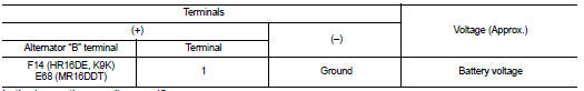
Is the inspection result normal? YES >> GO TO 3.
NO >> Check harness for open between alternator and fusible link.
3.CHECK “B” TERMINAL CONNECTION (VOLTAGE DROP TEST)
1. Start engine, then engine running at idle and warm.
2. Check voltage between battery positive terminal and alternator “B” terminal.
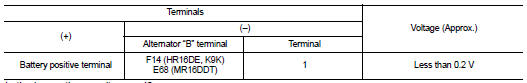
Is the inspection result normal? YES >> “B” terminal circuit is normal. Refer to CHG-12, "GASOLINE ENGINE MODELS : Work Flow" (gasoline engine models) or CHG-15, "DIESEL ENGINE MODELS : Work Flow" (diesel engine models).
NO >> Check harness between battery and alternator for poor continuity.

 L terminal circuit (open)
Description
The “L” terminal circuit controls the charge warning lamp. The charge warning
lamp illuminates when the ignition
switch is set to ON or START. When the alternator is providing suff ...
Other materials:
Diagnosis system [ABS actuator and electric unit (control
unit)]
CONSULT-III Function
APPLICATION ITEMS
CONSULT-III can display each diagnostic item using the diagnostic test modes
as follows.
*1: The following diagnosis information is erased by erasing.
• DTC
• Freeze frame data (FFD)
*2: Although “Function Test” is selectable, do not use its.
...
P1610 lock mode
Description
ECM forcibly switches to the mode that inhibits engine start, when engine
start operation is performed 5 times
or more while communication between ECM and BCM is not normal, or when engine
start operation is performed
5 times or more using the unregistered ignition key.
DTC Logic ...
P1612 chain of ECM-IMMU
DTC Logic
DTC DETECTION LOGIC
NOTE:
• If DTC P1612 is displayed with DTC U1000 (for BCM), first perform the trouble
diagnosis for DTC U1000.
Refer to BCS-153, "DTC Logic".
• If DTC P1612 is displayed with DTC U1010 (for BCM), first perform the trouble
diagnosis for DTC U1010 ...
