Nissan Juke Service and Repair Manual : Diagnosis system [ABS actuator and electric unit (control unit)]
CONSULT-III Function
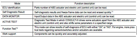
APPLICATION ITEMS
CONSULT-III can display each diagnostic item using the diagnostic test modes as follows.
*1: The following diagnosis information is erased by erasing.
• DTC
• Freeze frame data (FFD)
*2: Although “Function Test” is selectable, do not use its.
ECU IDENTIFICATION
ABS actuator and electric unit (control unit) part number can be read.
SELF DIAGNOSTIC RESULT
Refer to BRC-142, "DTC Index".
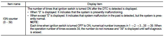
When “CRNT” is displayed on self-diagnosis result • The system is presently malfunctioning.
When “PAST” is displayed on self-diagnosis result • System malfunction in the past is detected, but the system is presently normal.
Freeze frame data (FFD)
When DTC is detected, a vehicle state shown below is recorded and displayed on
CONSULT-III.
DATA MONITOR
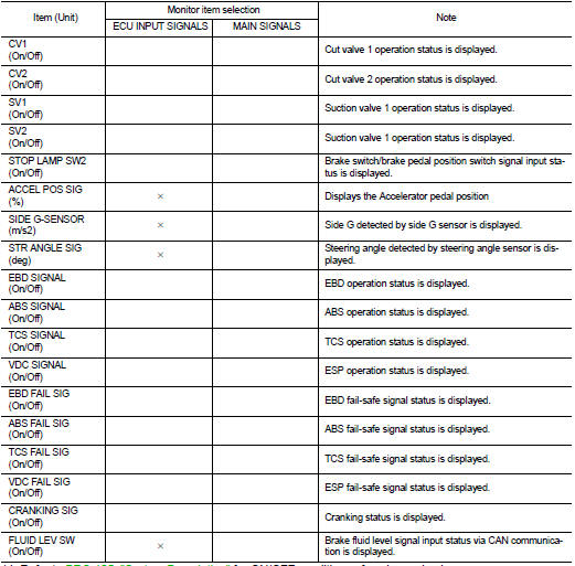
*1: Refer to BRC-105, "System Description" for ON/OFF conditions of each
warning lamp
.
*2: Models with CVT
ACTIVE TEST
The active test is used to determine and identify details of a malfunction, based on self-diagnosis test result sand data obtained in the DATA MONITOR. In response to instructions from CONSULT-III, instead of those from ABS actuator and electric unit (control unit) on the vehicle, a drive signal is sent to the actuator to check its operation.
CAUTION:
• Never perform ACTIVE TEST while driving the vehicle.
• Always bleed air from brake system before ACTIVE TEST.
• Never perform ACTIVE TEST when system is malfunctioning.
NOTE:
• When active test is performed while depressing the pedal, the pedal depressing stroke may change. This is not a malfunction.
• “TEST IS STOPPED” is displayed approx. 10 seconds after operation start.
• When performing active test again after “TEST IS STOPPED” is displayed, select “BACK”.
• ABS warning lamp and brake warning lamp may turn ON during active test. This is not a malfunction.
ABS IN Valve and ABS OUT Valve When “Up”, “Keep” or “Down” is selected on display screen, the following items are displayed when system is normal.
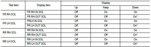
*: Immediately after being selected, status is “On”. Status changes to “Off” after approx. 2 seconds.
ABS IN Valve (ACT) and ABS OUT Valve (ACT) When “Up”, “ACT KEEP” or “ACT UP” is selected on display screen, the following items are displayed when system is normal.
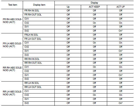
*: Immediately after being selected, status is “On”. Status changes to “Off” after approx. 2 seconds.
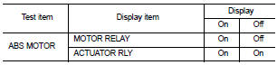
ABS Motor
When “On” or “Off” is selected on display screen, the following items are
displayed when system is normal.
 System
System Description
• The system switches fluid pressure of each brake caliper to increase, to
hold or to decrease according to
signals from control unit in ABS actuator and electric unit (contro ...
 ECU diagnosis information
ABS actuator and electric unit (control unit)
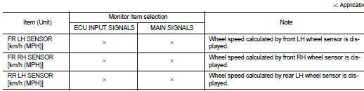
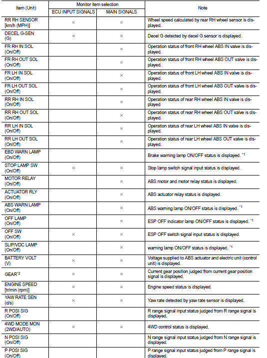
Reference Value
CONSULT-III DATA MONITOR STANDARD VALUE
*1: Confirm tire pressure is standard value.
*2: Refer to “valve operation” in BRC-1 ...
Other materials:
Front stabilizer
Exploded View
1. Stabilizer bar
2. Stabilizer clamp
3. Stabilizer bushing
4. Stabilizer connecting rod
5. Strut assembly
6. Front suspension member
: N·m (kg-m, ft-lb)
Removal and Installation
REMOVAL
1. Remove tires. Refer to WT-7, "Removal and Installation".
2. Remove f ...
Wheel alignment
Inspection
DESCRIPTION
Measure wheel alignment under unladen conditions.
NOTE:
“Unladen conditions” means that fuel, engine coolant, and lubricant are full.
Spare tire, jack, hand tools and
mats are in designated positions.
PRELIMINARY CHECK
Check the following:
• Tires for impro ...
Camshaft
Exploded View
1. Camshaft position sensor (PHASE)
2. O-ring
3. Camshaft bracket
4. Camshaft (EXH)
5. Camshaft sprocket (EXH)
6. Camshaft sprocket (INT)
7. Camshaft (INT)
8. Valve lifter (EXH)
9. Valve lifter (INT)
10. Signal plate (INT)
11 Signal plate (EXH)
A.Tightening must be ...
