Nissan Juke Service and Repair Manual : L terminal circuit (open)
Description
The “L” terminal circuit controls the charge warning lamp. The charge warning lamp illuminates when the ignition switch is set to ON or START. When the alternator is providing sufficient voltage with the engine running, the charge warning lamp will go off. If the charge warning lamp illuminates with the engine running, a malfunction is indicated.
Diagnosis Procedure
1.CHECK “L” TERMINAL CONNECTION
1. Turn ignition switch OFF.
2. Check if “L” terminal is clean and tight.
Is the inspection result normal? YES >> GO TO 2.
NO >> Repair “L” terminal connection.
2.CHECK “L” TERMINAL CIRCUIT (OPEN)
1. Disconnect alternator connector.
2. Apply ground to alternator harness connector terminal.
3. Check condition of the charge warning lamp with the ignition switch in the ON position.
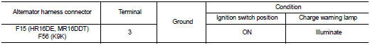
Does it illuminate? YES >> “L” terminal circuit is normal. Refer to CHG-12, "GASOLINE ENGINE MODELS : Work Flow" (gasoline engine models) or CHG-15, "DIESEL ENGINE MODELS : Work Flow" (diesel engine models).
NO >> GO TO 3.
3.CHECK HARNESS CONTINUITY (OPEN CIRCUIT)
1. Disconnect the battery cable from the negative terminal.
2. Disconnect the combination meter connector.
3. Check continuity between alternator harness connector and combination meter harness connector.
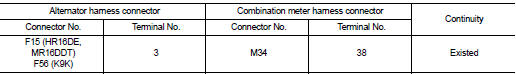
Is the inspection result normal? YES >> GO TO 4.
NO >> Repair the harness or connector.
4.CHECK HARNESS CONTINUITY (OPEN CIRCUIT)
Check continuity between combination meter harness connector M34 terminal 28 and 10A fuse [No.5 located in the fuse block (J/B)].
Does continuity exist? YES >> GO TO 5.
NO >> Repair the harness.
5.CHECK POWER SUPPLY CIRCUIT
1. Connect the battery cable to the negative terminal.
2. Check voltage between combination meter harness connector and ground.
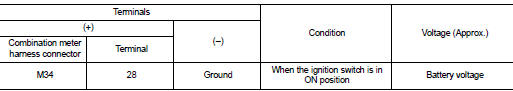
Is the inspection result normal? YES >> Replace combination meter.
NO >> Inspect the power supply circuit. Refer to PG-15, "Wiring Diagram - IGNITION POWER SUPPLY - ".
 B terminal circuit
Description
“B” terminal circuit supplies power to charge the battery and to operate the
vehicle’s electrical system.
Diagnosis Procedure
1.CHECK “B” TERMINAL CONNECTION
1. Turn igniti ...
 L terminal circuit (short)
Description
The “L” terminal circuit controls the charge warning lamp. The charge warning
lamp illuminates when the ignition
switch is set to ON or START. When the alternator is providing suff ...
Other materials:
Back door opener switch
Component Function Check
1.CHECK FUNCTION
1. Select “TRUNK” of “BCM” using CONSULT-III.
2. Select “TRNK OPNR SW” in “DATA MONITOR” mode.
3. Check that the function operates normally according to the following
conditions.
Is the inspection result normal?
YES >> Back do ...
Input shaft and gear
Exploded View
1. Input shaft front bearing
2. Input shaft
3. 3rd input gear
4. Spacer
5. Snap ring
6. 3rd baulk ring
7. 3rd-4th coupling sleeve
8. 3rd-4th synchronizer hub
9. Insert key
10. 4th baulk ring
11. 4th input gear
12. 5th input gear
13. 5th baulk ring
14. 5th-6th c ...
Precaution for Seat Belt Service
CAUTION:
• Before removing the front seat belt pre-tensioner assembly, turn the ignition
switch off, disconnect
battery negative terminal and wait at least 3 minutes.
• Do not use electrical test equipment for front seat belt pre-tensioner
connector.
• After replacing or reinstalling f ...
