Nissan Juke Service and Repair Manual : Input shaft and gear
Exploded View
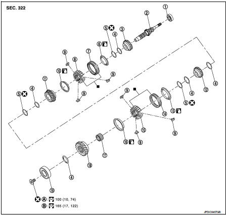
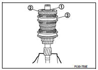
1. Input shaft front bearing
2. Input shaft
3. 3rd input gear
4. Spacer
5. Snap ring
6. 3rd baulk ring
7. 3rd-4th coupling sleeve
8. 3rd-4th synchronizer hub
9. Insert key
10. 4th baulk ring
11. 4th input gear
12. 5th input gear
13. 5th baulk ring
14. 5th-6th coupling sleeve
15. 5th-6th synchronizer hub
16. 6th baulk ring
17. Needle bearing 18. 6th input gear
19. Input shaft rear bearing
A. First step B. Final step
 : Apply gear oil.
 : Replace the parts as a set.
 : Always replace after every
disassembly.
 : N·m (kg-m, ft-lb)
Disassembly
CAUTION:
• Fix input shaft in a vise with back plate, and then remove gears and snap
rings.
• For removal of snap ring, set snap ring pliers and flat pliers at both sides of snap ring. While expanding snap ring with snap ring pliers, move snap ring with flat pliers.
• Disassemble gear components putting direction marks on the parts that do not affect any functions.
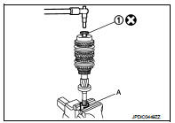
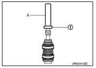
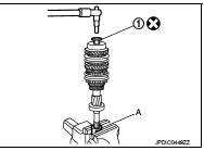
1. Remove input shaft rear bearing mounting bolt (1), using the drift (A) [SST: KV32300QAM].
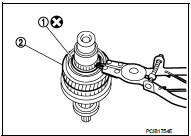
2. Remove input shaft rear bearing (1), as per the following procedure.
a. Set a puller [Commercial service tool] to input shaft rear bearing.
b. Remove input shaft rear bearing, using a drift (A) [Commercial service tool].
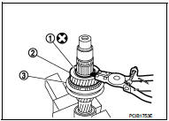
3. Remove spacer (1), 6th input gear (2), needle bearing, 6th baulk ring, and 5th-6th synchronizer hub assembly (3).
4. Remove insert keys and 5th-6th coupling sleeve from 5th-6th synchronizer hub.
5. Remove snap ring (1).
6. Remove spacer, 5th baulk ring, 5th input gear (2), and spacer.
7. Remove snap ring (1).
8. Remove spacer, 4th input gear (2), 4th baulk ring, and 3rd-4th synchronizer hub assembly (3).
9. Remove insert keys and 3rd-4th coupling sleeve from 3rd-4th synchronizer hub.
10. Remove snap ring (1).
11. Remove spacer, 3rd baulk ring, and 3rd input gear (2).
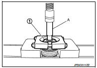
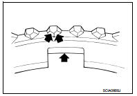
![12. Set a puller [Commercial service tool] to input shaft front bearing](images/books/335/26/index226.jpg)
12. Set a puller [Commercial service tool] to input shaft front bearing (1), and then remove input shaft front bearing.
Assembly
Note the following procedures, and assemble in the reverse order of disassembly.
CAUTION:
• Replace transaxle assembly when replacing input shaft.
• For installation of snap ring, set snap ring pliers and flat pliers at both sides of snap ring. While expanding snap ring with snap ring pliers, move snap ring with flat pliers.
• Never reuse snap ring.
• Check that snap ring is securely installed in a groove.
• Replace 3rd-4th coupling sleeve and 3rd-4th synchronizer hub as a set.
• Replace 5th-6th coupling sleeve and 5th-6th synchronizer hub as a set.
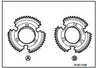
• Be careful to install 3rd-4th synchronizer hub according to the specified direction.
A : 3rd input gear side B : 4th input gear side
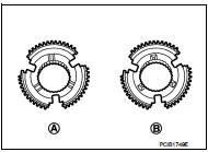
• Be careful to install 5th-6th synchronizer hub according to the specified direction.
A : 5th input gear side B : 6th input gear side
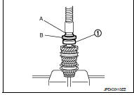
• Install input shaft front bearing (1), using a drift (A) [Commercial service tool].
• Install input shaft rear bearing (1), using a drift (A) [Commercial service tool] and the drift (B) [SST: ST36720030].
• Apply gear oil to 3rd baulk ring, 4th baulk ring, 5th baulk ring, and 6th baulk ring.
• Install input shaft rear bearing mounting bolt (1), as per the following procedure.
CAUTION:
Follow the procedures. Otherwise it may cause a transaxle
malfunction.
1. Fix the drift (A) [SST: KV32300QAM] in a vise, and then set input shaft assembly.
2. Install input shaft rear bearing mounting bolt, and then tighten it to the specified torque of the first step.
3. Loosen input shaft rear bearing mounting bolt by a half turn.
4. Tighten input shaft rear bearing mounting bolt to the specified torque of the final step.
Inspection
INSPECTION AFTER DISASSEMBLY
Input Shaft and Gear
Check the following items and replace if necessary.
• Damage, peeling, bend, uneven wear, and distortion of shaft.
• Excessive wear, damage, and peeling of gear.
Synchronizer Hub and Coupling Sleeve Check the following items and replace if necessary.
• Breakage, damage, and unusual wear on contact surface of coupling sleeve, synchronizer hub, and insert key.
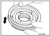
• Coupling sleeve and synchronizer hub move smoothly.
Baulk Ring
Check contact surface of baulk ring cam and insert key for excessive
wear, uneven wear, bend, and damage. Replace if necessary.
Bearing
Check bearing for damage and unsmooth rotation. Replace if necessary.
 Transaxle assembly
Exploded View
CASE AND HOUSING
1. Filler plug
2. Gasket
3. Transaxle case
4. Bushing
5. Snap ring
6. Oil channel
7. Oil gutter
8. Position switch
9. Bracket
10. Differential side oi ...
 Mainshaft and gear
Exploded View
1. Mainshaft front bearing outer
race
2. Mainshaft front bearing inner race
3. Mainshaft
4. 1st main gear
5. 1st inner baulk ring
6. 1st synchronizer cone
7. 1st outer baulk r ...
Other materials:
Oil seal
Valve oil seal
VALVE OIL SEAL : Removal and Installation
REMOVAL
1. Remove camshafts. Refer to EM-191, "Exploded View".
2. Remove valve lifters. Refer to EM-191, "Exploded View".
3. Rotate crankshaft, and set piston whose valve oil seal is to be removed to
TDC. This will p ...
Additional service when replacing
ECM
Description
When replacing ECM, this procedure must be performed.
Work Procedure
1.PERFORM INITIALIZATION OF NATS SYSTEM AND REGISTRATION OF ALL NATS
IGNITION KEY IDS
Refer to SEC-50, "ECM : Work Procedure".
>> GO TO 2.
2.PERFORM ACCELERATOR PEDAL RELEASED POSITION LEARNIN ...
Dynamic driver assistance switch
(for vehicles without ProPILOT Assist)
The physical dynamic driver assistance switch allows the operator to temporarily activate or deactivate the advanced Intelligent Lane Intervention (I-LI) and Intelligent Blind Spot Intervention (I-BSI) safety systems, assuming these safety features have already been enabled wit ...
