Nissan Juke Service and Repair Manual : Intake valve timing control
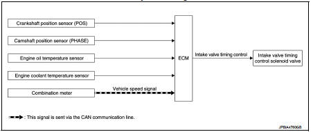
Intake valve timing control : System Diagram
Intake valve timing control : System Description
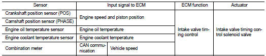
INPUT/OUTPUT SIGNAL CHART
SYSTEM DESCRIPTION
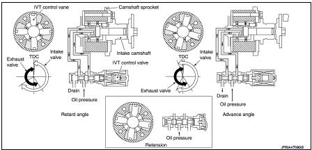
This mechanism hydraulically controls cam phases continuously with the fixed operating angle of the intakevalve.
The ECM receives signals such as crankshaft position, camshaft position, engine speed, and engine coolanttemperature.
Then, the ECM sends ON/OFF pulse duty signals to the intake valve timing (IVT) control solenoid valve depending on driving status. This makes it possible to control the shut/open timing of the intake valve to increase engine torque in low/mid speed range and output in high-speed range.
 Electric ignition system
Electric ignition system : System Diagram
Electric ignition system : System Description
INPUT/OUTPUT SIGNAL CHART
*1: CVT models
*2: M/T models
*3: ECM determines the start signa ...
 Exhaust valve timing control
Exhaust valve timing control : System Diagram
Exhaust valve timing control: System Description
INPUT/OUTPUT SIGNAL CHART
SYSTEM DESCRIPTION
This mechanism hydraulically controls cam phases c ...
Other materials:
Doors
WARNING
• Always have the doors locked while driving. Along with the use of
seat belts, this provides greater safety in the event of an accident by helping
to prevent persons from being thrown from the vehicle. This also helps keep children
and others from unintentionally opening the ...
Component parts
Component Parts Location
1. Combination meter
2. Intelligent Key warning buzzer
3. Push-button ignition switch
4. Inside key antenna (instrument center)
5. TCM
Refer to TM-133, "CVT CONTROL
SYSTEM : TCM" (RE0F10B models)
or TM-316, "CVT CONTROL SYSTEM
: TCM" (RE0F11 ...
Wiring diagram
NISSAN DYNAMIC CONTROL SYSTEM
Wiring Diagram
For connector terminal arrangements, harness layouts, and alphabets in a
(option abbreviation; if not
described in wiring diagram), refer to GI-12, "Connector Information/Explanation
of Option Abbreviation".
...
