Nissan Juke Service and Repair Manual : Illumination
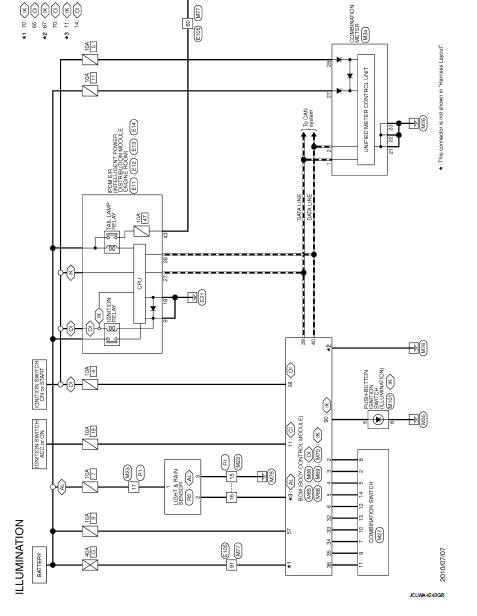
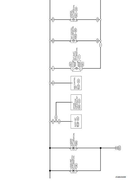
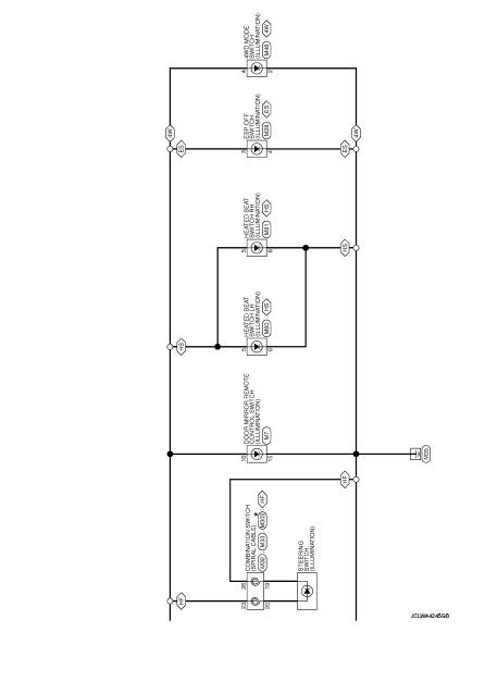
Wiring Diagram
For connector terminal arrangements, harness layouts, and alphabets in a
 (option abbreviation: if not
described in wiring diagram), refer to GI-12, "Connector Information/Explanation
of Option Abbreviation".
 Interior room lamp control system
Wiring Diagram
For connector terminal arrangements, harness layouts, and alphabets in a
(option abbreviation: if not
described in wiring diagram), refer to GI-12, "Connector Information/Explan ...
 Basic inspection
DIAGNOSIS AND REPAIR WORKFLOW
Work Flow
OVERALL SEQUENCE
DETAILED FLOW
1.INTERVIEW FOR MALFUNCTION
Interview the symptom to the customer.
>> GO TO 2.
2.SYMPTOM CHECK
Check the sympto ...
Other materials:
Precaution
Precaution for Supplemental Restraint System (SRS) "AIR BAG" and "SEAT BELT
PRE-TENSIONER"
The Supplemental Restraint System such as ŌĆ£AIR BAGŌĆØ and ŌĆ£SEAT BELT PRE-TENSIONERŌĆØ,
used along
with a front seat belt, helps to reduce the risk or severity of injury to the
dr ...
Exploded View
1. Final drive mounting bracket
2. Washer
3. Rear final drive assembly
: Vehicle front
: N┬Ęm (kg-m, ft-lb)
: Never reuse parts
: Apply multi purpose grease
: Apply gear oil.
...
Transaxle assembly
Exploded View
CASE AND HOUSING
1. Filler plug
2. Gasket
3. Transaxle case
4. Bushing
5. Snap ring
6. Oil channel
7. Oil gutter
8. Position switch
9. Bracket
10. Differential side oil seal
11. Magnet
12. Drain plug
13. Input shaft oil seal
14. Clutch housing
15. 2 way conn ...
