Nissan Juke Service and Repair Manual : B2605 shift position
DTC Logic
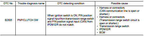
DTC DETECTION LOGIC
NOTE
:
ÔÇó If DTC B2605 is displayed with DTC U1000, first perform the trouble diagnosis
for DTC U1000. Refer to
BCS-83, "DTC Logic".
ÔÇó If DTC B2605 is displayed with DTC U1010, first perform the trouble diagnosis for DTC U1010. Refer to BCS-84, "DTC Logic".
DTC CONFIRMATION PROCEDURE
1.PERFORM DTC CONFIRMATION PROCEDURE
1. Shift the selector lever to the P position.
2. Turn ignition switch ON and wait 1 second or more.
3. Shift the selector lever to the N position and wait 1 second or more.
4. Shift the selector lever to any position other than P and N, and wait 1 second or more.
5. Check DTC in ÔÇťSelf Diagnostic ResultÔÇŁ mode of ÔÇťBCMÔÇŁ using CONSULT-III.
Is DTC detected? YES >> Go to SEC-90, "Diagnosis Procedure".
NO >> INSPECTION END
Diagnosis Procedure
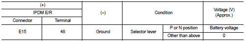
1.CHECK IPDM E/R INPUT SIGNAL
1. Turn ignition switch OFF.
2. Disconnect IPDM E/R connector.
3. Turn ignition switch ON.
4. Check voltage between IPDM E/R harness connector and ground.
Is the inspection result normal? YES >> GO TO 3.
NO >> GO TO 2.
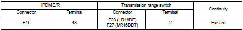
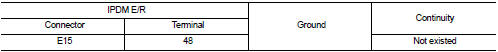
2.CHECK IPDM E/R INPUT SIGNAL CIRCUIT
1. Turn ignition switch OFF.
2. Disconnect transmission range switch connector.
3. Check continuity between IPDM E/R harness connector and BCM harness connector.
4. Check continuity between IPDM E/R harness connector and ground.
Is the inspection result normal? YES >> GO TO 6.
NO >> Repair or replace harness.
3.CHECK BCM INPUT SIGNAL
1. Turn ignition switch OFF.
2. Disconnect BCM connector.
3. Turn ignition switch ON.
4. Check voltage between BCM harness connector and ground.
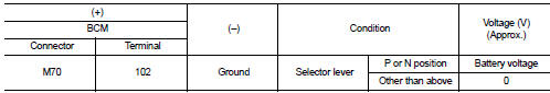
Is the inspection result normal? YES >> GO TO 5.
NO >> GO TO 4.
4.CHECK BCM INPUT SIGNAL CIRCUIT
1. Turn ignition switch OFF.
2. Disconnect transmission range switch connector.
3. Disconnect BCM connector.
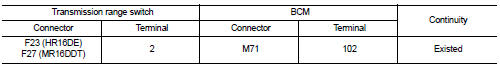
4. Check continuity between transmission range switch harness connector and BCM harness connector.
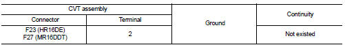
5. Check continuity between CVT assembly harness connector and ground.
Is the inspection result normal? YES >> GO TO 6.
NO >> Repair or replace harness.
5.REPLACE BCM
1. Replace BCM. Refer to BCS-93, "Removal and Installation".
2. Perform initialization of BCM and registration of all Intelligent Keys using CONSULT-III.
For initialization and registration procedures, refer to CONSULT-III Operation Manual NATS-IVIS/NVIS.
3. Perform DTC CONFIRMATION PROCEDURE for DTC B2605. Refer to SEC-90, "DTC Logic".
Is DTC B2605 detected again? YES >> Replace IPDM E/R. Refer to PCS-34, "Removal and Installation".
NO >> INSPECTION END
6.CHECK INTERMITTENT INCIDENT
Refer to GI-42, "Intermittent Incident".
>> INSPECTION END
 B2604 shift position
DTC Logic
DTC DETECTION LOGIC
NOTE:
ÔÇó If DTC B2604 is displayed with DTC U1000, first perform the trouble diagnosis
for DTC U1000. Refer to
BCS-83, "DTC Logic".
ÔÇó If DTC B2604 is ...
 B2608 starter relay
DTC Logic
DTC DETECTION LOGIC
NOTE:
ÔÇó If DTC B2608 is displayed with DTC U1000, first perform the trouble diagnosis
for DTC U1000. Refer to
BCS-83, "DTC Logic".
ÔÇó If DTC B2608 is ...
Other materials:
Removal and Installation
REMOVAL
ÔÇó Disconnect each joint and mounting.
ÔÇó Remove heated oxygen sensor 2 with following procedure:
- Using heated oxygen sensor wrench [SST: KV10114400] (A),
removal heated oxygen sensor 2 (1).
CAUTION:
Be careful not to damage heated oxygen sensor 2.
INSTALLATION
Note the follo ...
Rear window defogger switch
With auto A/C
WITH AUTO A/C : Description
ÔÇó The rear window defogger is operated by turning the rear window defogger
switch ON.
ÔÇó The indicator lamp in the rear window defogger switch illuminates when the
rear window defogger is operating.
WITH AUTO A/C : Component Function Check
1.CHEC ...
Super lock actuator
Driver side : Component Function Check
1.CHECK FUNCTION
1. Select ÔÇťDOOR LOCKÔÇŁ of ÔÇťBCMÔÇŁ using CONSULT-III.
2. Select ÔÇťSUPER LOCKÔÇŁ in ÔÇťACTIVE TESTÔÇŁ mode.
3. Check that the function operates normally according to the following
conditions.
Is the inspection result normal?
YES & ...
