Nissan Juke Service and Repair Manual : Rear wiper motor circuit
Component Function Check
1.CHECK REAR WIPER ON OPERATION
 CONSULT-III ACTIVE TEST
1. Select “RR WIPER” of BCM active test item.
2. With operating the test item, check rear wiper operation.
On : Rear wiper ON operation Off : Stop the rear wiper.
Is rear wiper operation normally? YES >> Rear wiper motor circuit is normal.
NO >> Refer to WW-45, "Diagnosis Procedure".
Diagnosis Procedure
1.CHECK REAR WIPER MOTOR OUTPUT VOLTAGE
 CONSULT-III ACTIVE TEST
1. Turn ignition switch OFF.
2. Disconnect rear wiper motor connector.
3. Turn ignition switch ON.
4. Select “RR WIPER” of BCM active test item.
5. With operating the test item, check voltage between rear wiper motor harness connector and ground.
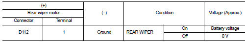
Is the inspection result normal? YES >> GO TO 3.
NO >> GO TO 2.
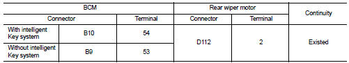
2.CHECK REAR WIPER MOTOR CIRCUIT
1. Turn ignition switch OFF.
2. Disconnect BCM connector.
3. Check continuity between BCM harness connector and rear wiper motor harness connector.
4. Check continuity between BCM harness connector and ground.
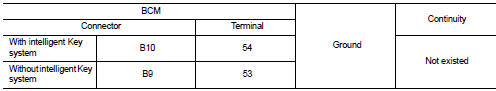
Is the inspection result normal? YES >> Replace BCM. Refer to BCS-93, "Removal and Installation".
NO >> Repair or replace harness.
3.CHECK REAR WIPER MOTOR GROUND OPEN CIRCUIT
Check continuity between rear wiper motor harness connector and ground.
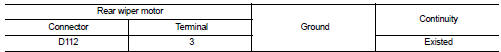
Is the inspection result normal? YES >> Replace rear wiper motor.
NO >> Repair or replace harness.
 Washer switch
Component Inspection
1.CHECK WASHER SWITCH
1. Turn ignition switch OFF.
2. Disconnect combination switch connector.
3. Check continuity between the combination switch terminals.
A : Terminal 4
B ...
 Rear wiper auto stop signal circuit
Component Function Check
1.CHECK REAR WIPER (AUTO STOP) OPERATION
CONSULT-III DATA MONITOR
1. Select “WIPER” of BCM data monitor item.
2. Operate the rear wiper.
3. Check that “RR WIPER STO ...
Other materials:
B1215, B1216, B1217 satellite sensor LH
DTC Logic
DTC DETECTION LOGIC
DTC CONFIRMATION PROCEDURE
1.CHECK SELF-DIAG RESULT
With CONSULT-III
1. Turn ignition switch ON.
2. Perform “Self Diagnostic Result” mode of “AIR BAG” using CONSULT-III.
Without CONSULT-III
1. Turn ignition switch ON.
2. Check the air bag warning la ...
Main line between ipdm-e and dlc circuit
Diagnosis Procedure
1.CHECK CONNECTOR
1. Turn the ignition switch OFF.
2. Disconnect the battery cable from the negative terminal.
3. Check the following terminals and connectors for damage, bend and loose
connection (connector side
and harness side).
- Harness connector E105
- Harness co ...
P1078 EVT control position sensor
DTC Logic
DTC DETECTION LOGIC
DTC CONFIRMATION PROCEDURE
1.PRECONDITIONING
If DTC Confirmation Procedure has been previously conducted, always perform
the following procedure
before conducting the next test.
1. Turn ignition switch OFF and wait at least 10 seconds.
2. Turn ignition swit ...
