Nissan Juke Service and Repair Manual : Rear wiper auto stop signal circuit
Component Function Check
1.CHECK REAR WIPER (AUTO STOP) OPERATION
 CONSULT-III DATA MONITOR
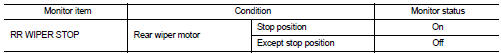
1. Select “WIPER” of BCM data monitor item.
2. Operate the rear wiper.
3. Check that “RR WIPER STOP” changes to “On” and “Off” linked with the wiper operation.
Is the status of item normal? YES >> Rear wiper auto stop signal circuit is normal.
NO >> Refer to WW-47, "Diagnosis Procedure".
Diagnosis Procedure
1.CHECK REAR WIPER MOTOR (AUTO STOP) OUTPUT VOLTAGE
1. Turn ignition switch OFF.
2. Disconnect rear wiper motor connector.
3. Turn ignition switch ON.
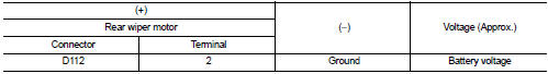
4. Check voltage between rear wiper motor harness connector and ground.
Is the inspection result normal? YES >> Replace rear wiper motor.
NO >> GO TO 2.
2.CHECK REAR WIPER MOTOR (AUTO STOP) CIRCUIT
1. Turn ignition switch OFF.
2. Disconnect BCM connector.
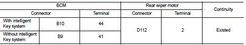
3. Check continuity between BCM harness connector and rear wiper motor harness connector.
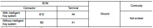
4. Check continuity between BCM harness connector and ground.
Is the inspection result normal?
YES >> Replace BCM. Refer to BCS-93, "Removal and Installation".
NO >> Repair or replace harness.
 Rear wiper motor circuit
Component Function Check
1.CHECK REAR WIPER ON OPERATION
CONSULT-III ACTIVE TEST
1. Select “RR WIPER” of BCM active test item.
2. With operating the test item, check rear wiper operation.
On ...
 Headlamp washer relay
Component Inspection
1.CHECK HEADLAMP WASHER RELAY
1. Turn the ignition switch OFF.
2. Remove headlamp washer relay.
3. Apply battery voltage to headlamp washer relay between terminals 1 and 2.
4 ...
Other materials:
The ambient temperature display is incorrect
Description
• The displayed ambient air temperature is higher than the actual
temperature.
• The displayed ambient air temperature is lower than the actual temperature.
Diagnosis Procedure
NOTE:
Check that the symptom is not applicable to the normal operating condition
before starting d ...
Precautions For Refrigerant System Service
GENERAL REFRIGERANT PRECAUTION
WARNING:
• Never breathe A/C refrigerant and lubricant vapor or mist. Exposure may
irritate eyes, nose and
throat. Use only approved recovery/recycling equipment to discharge HFC-134a
(R-134a) refrigerant.
Ventilate work area before resuming service if acci ...
P0090 fuel pump
DTC Logic
DTC DETECTION LOGIC
Diagnosis Procedure
1.CHECK HIGH PRESSURE SUPPLY PUMP (PRESSURE CONTROL VALVE) POWER SUPPLY
1. Turn ignition switch OFF.
2. Disconnect high pressure supply pump (pressure control valve) harness
connector.
3. Turn ignition switch ON.
4. Check the voltage betwe ...
