Nissan Juke Service and Repair Manual : U1000 can comm circuit
Description
CAN (Controller Area Network) is a serial communication line for real time applications. It is an on-board multiplex communication line with high data communication speed and excellent error detection ability. A modern vehicle is equipped with many ECUs, and each control unit shares information and links with other control units during operation (not independent). In CAN communication, 2 control units are connected with 2 communication lines (CAN-L-line and CAN-H-line) allowing a high rate of information transmission with less wiring.
Each control unit transmits/receives data but selectively reads required data only.
Refer to LAN-31, "CAN COMMUNICATION SYSTEM : CAN Communication Signal Chart" for details of the communication signal.
DTC Logic
DTC DETECTION LOGIC
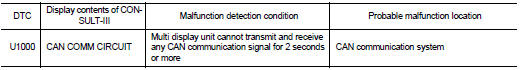
Diagnosis Procedure
1.PERFORM SELF-DIAGNOSIS
1. Turn the ignition switch ON and hold it for 2 seconds or more.
2. Using CONSULT-III, check the ŌĆØself diagnosis resultŌĆ£ of ŌĆØMULTI DISPLAYŌĆ£.
Is CAN communication system displayed? YES >> Refer to LAN-17, "Trouble Diagnosis Flow Chart".
NO >> Refer to GI-42, "Intermittent Incident".

 U1010 control unit (can)
Description
Initial diagnosis of multi display unit
DTC Logic
DTC DETECTION LOGIC
Diagnosis Procedure
1.REPLACE THE MULTI DISPLAY UNIT
If DTC U1010 is detected, replace the multi display unit. ...
Other materials:
Back door does not opened
Diagnosis Procedure
1.CHECK BACK DOOR OPENER SWITCH
Check back door opener switch.
Refer to DLK-244, "Component Function Check".
Is the inspection result normal?
YES >> GO TO 2.
NO >> Repair or replace the malfunctioning parts.
2.CHECK BACK DOOR OPENER ACTUATOR
...
ASCD steering switch
Component Function Check
1.CHECK ASCD STEERING SWITCH FUNCTION
1. Turn ignition switch ON.
2. Check the voltage between ECM harness connector terminals under the following
conditions.
Is the inspection result normal?
YES >> INSPECTION END
NO >> Go to EC-1011, "Diagnosis Pr ...
Basic inspection
Diagnosis and repair work flow
Work Flow
DETAILED FLOW
1.INTERVIEW FROM THE CUSTOMER
Clarify customer complaints before inspection. First of all, perform an
interview utilizing BRC-34, "Diagnostic
Work Sheet" and reproduce the symptom as well as fully understand it. Ask
customer a ...
