Nissan Juke Service and Repair Manual : U1010 control unit (can)
Description
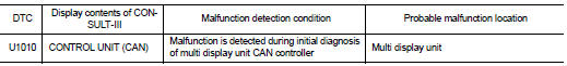
Initial diagnosis of multi display unit
DTC Logic
DTC DETECTION LOGIC
Diagnosis Procedure
1.REPLACE THE MULTI DISPLAY UNIT
If DTC U1010 is detected, replace the multi display unit. AV-125, "Removal and Installation".
>> INSPECTION END
 U1000 can comm circuit
Description
CAN (Controller Area Network) is a serial communication line for real time
applications. It is an on-board multiplex
communication line with high data communication speed and excellent ...
 U1402 engine speed signal
DTC Logic
DTC DETECTION LOGIC
Diagnosis Procedure
1.PERFORM ECM SELF DIAGNOSIS
Using CONSULT-III, check the ãself diagnosis resultã of ãENGINEã and repair
or replace any malfunctioning ...
Other materials:
C1606 EPS motor
DTC Logic
DTC DETECTION LOGIC
DTC CONFIRMATION PROCEDURE
1.PRECONDITIONING
If ãDTC CONFIRMATION PROCEDUREã has been previously conducted, always turn
ignition switch OFF and
wait at least 10 seconds before conducting the next test.
>> GO TO 2.
2.DTC REPRODUCTION PROCEDURE
W ...
C1101, C1102, C1103, C1104 WHEEL SENSOR
DTC Logic
DTC DETECTION LOGIC
DTC CONFIRMATION PROCEDURE
1.PRECONDITIONING
If ãDTC CONFIRMATION PROCEDUREã has been previously conducted, always turn
ignition switch OFF and
wait at least 10 seconds before conducting the next test.
>> GO TO 2.
2.CHECK DTC DETECTION
With CON ...
Wiring diagram
AUTOMATIC AIR CONDITIONING SYSTEM
Wiring Diagram
For connector terminal arrangements, harness layouts, and alphabets in a
(option abbreviation; if not
described in wiring diagram), refer to GI-12, "Connector Information/Explanation
of Option Abbreviation".
...
