
Nissan Juke Service and Repair Manual : Wiring diagram
AUTOMATIC AIR CONDITIONING SYSTEM
Wiring Diagram
For connector terminal arrangements, harness layouts, and alphabets in a
 (option abbreviation; if not
described in wiring diagram), refer to GI-12, "Connector Information/Explanation
of Option Abbreviation".

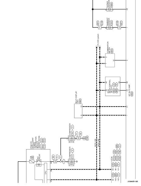
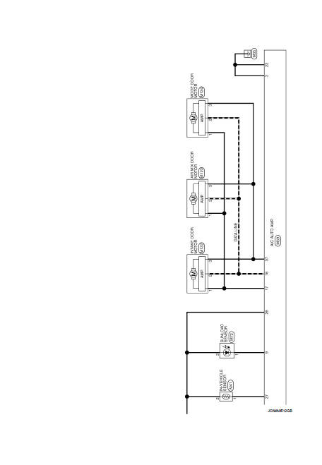
 Multi display unit, BCM, ECM, IPDM E/R
List of ECU Reference
...
 Basic inspection
...
Other materials:
B2205 vehicle speed
Description
Vehicle speed signal is transmitted from ABS actuator and electric unit
(control unit) via CAN communication
to combination meter.
DTC Logic
DTC DETECTION LOGIC
Diagnosis Procedure
1.PERFORM SELF-DIAGNOSIS OF ABS ACTUATOR AND ELECTRIC UNIT (CONTROL UNIT)
Perform “Self Diagno ...
Removal and installation
Exhaust system
Exploded View
2WD
1. Center muffler
2. Mounting rubber
3. Spring
4. Seal bearing
5. Stud bolt
6. Three way catalyst
7. Heated oxygen sensor 2
8. Seal bearing
9. Ring gasket
10. Main muffler
A. To catalyst convertor
: N·m (kg-m, ft-lb)
: Always replace after eve ...
B210B starter control relay
DTC Logic
DTC DETECTION LOGIC
NOTE:
If DTC B210B is displayed with DTC U1000, first perform the trouble diagnosis
for DTC U1000. Refer to PCS-
30, "DTC Logic".
DTC CONFIRMATION PROCEDURE
1.PERFORM DTC CONFIRMATION PROCEDURE
1. Press push-button ignition switch under the followin ...
