Nissan Juke Service and Repair Manual : Main line between ipdm-e and dlc circuit
Diagnosis Procedure
1.CHECK CONNECTOR
1. Turn the ignition switch OFF.
2. Disconnect the battery cable from the negative terminal.
3. Check the following terminals and connectors for damage, bend and loose connection (connector side and harness side).
- Harness connector E105 - Harness connector M77
Is the inspection result normal? YES >> GO TO 2.
NO >> Repair the terminal and connector.
2.CHECK HARNESS CONTINUITY (OPEN CIRCUIT)
1. Disconnect the following harness connectors.
- IPDM E/R
- Harness connectors E105 and M77
2. Check the continuity between the IPDM E/R harness connector and the harness
connector.
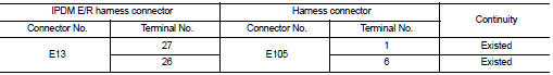
Is the inspection result normal? YES >> GO TO 3.
NO >> Repair the main line between the IPDM E/R and the harness connector E105.
3.CHECK HARNESS CONTINUITY (OPEN CIRCUIT)
Check the continuity between the harness connector and the data link connector.
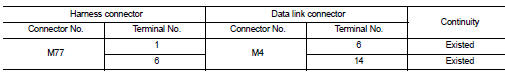
Is the inspection result normal? YES (Present error)>>Check CAN system type decision again.
YES (Past error)>>Error was detected in the main line between the IPDM E/R and the data link connector.
NO >> Repair the main line between the harness connector M77 and the data link connector.
 Malfunction area chart
Main Line
Branch Line
Short Circuit
...
 Main line between DLC and A-bag circuit
Diagnosis Procedure
1.CHECK HARNESS CONTINUITY (OPEN CIRCUIT)
1. Turn the ignition switch OFF.
2. Disconnect the battery cable from the negative terminal.
3. Disconnect the BCM harness connector.
...
Other materials:
P1813 4WD mode switch
DTC Logic
DTC DETECTION LOGIC
DTC CONFIRMATION PROCEDURE
1.PRECONDITIONING
If “DTC CONFIRMATION PROCEDURE” has been previously conducted, always turn
ignition switch OFF and
wait at least 10 seconds before conducting the next test.
>> GO TO 2.
2.DTC REPRODUCTION PROCEDURE
W ...
Vehicle speed sensing auto lock operation does not operate
Diagnosis Procedure
1.CHECK “AUTOMATIC LOCK/UNLOCK SELECT” SETTING IN “WORK SUPPORT”
1. Select “DOOR LOCK” of “BCM” using CONSULT-III.
2. Select “AUTOMATIC LOCK/UNLOCK SELECT” in “WORK SUPPORT” mode.
3. Check “AUTOMATIC LOCK/UNLOCK SELECT” setting in “WORK SUPPORT†...
Preparation
Special Service Tools
BASIC INSPECTION
STEERING WHEEL
Inspection
NEUTRAL POSITION STEERING WHEEL
1. Make sure that steering gear assembly, steering column assembly and
steering wheel are installed in the
correct position.
2. Perform neutral position inspection after wheel alignment. Refer ...
