Nissan Juke Service and Repair Manual : Main line between DLC and A-bag circuit
Diagnosis Procedure
1.CHECK HARNESS CONTINUITY (OPEN CIRCUIT)
1. Turn the ignition switch OFF.
2. Disconnect the battery cable from the negative terminal.
3. Disconnect the BCM harness connector.
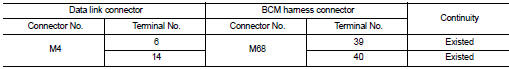
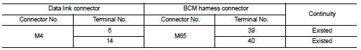
4. Check the continuity between the data link connector and the BCM harness connector.
- With Intelligent Key system
- Without Intelligent Key system
Is the inspection result normal? YES (Present error)>>Check CAN system type decision again.
YES (Past error)>>Error was detected in the main line between the data link connector and the air bag diagnosis sensor unit.
NO >> Repair the main line between the data link connector and the air bag diagnosis sensor unit.
 Main line between ipdm-e and dlc circuit
Diagnosis Procedure
1.CHECK CONNECTOR
1. Turn the ignition switch OFF.
2. Disconnect the battery cable from the negative terminal.
3. Check the following terminals and connectors for damage, bend ...
 Main line betweeN DLC and MDU circuit
Diagnosis Procedure
1.CHECK HARNESS CONTINUITY (OPEN CIRCUIT)
1. Turn the ignition switch OFF.
2. Disconnect the battery cable from the negative terminal.
3. Disconnect the following harness conne ...
Other materials:
Both side headlamps (HI) are not turned on
Description
Both side headlamps (HI) are not turned ON when setting to the lighting
switch HI or PASS.
Diagnosis Procedure
1.COMBINATION SWITCH INSPECTION
Check the combination switch. Refer to BCS-92, "Symptom Table".
Is the inspection result normal?
YES >> GO TO 2.
NO ...
Security indicator lamp does not turn on or blink
Description
Security indicator lamp does not blink when ignition switch is in a position
other than ON.
NOTE:
• Before performing the diagnosis, check “Work Flow”. Refer to SEC-47, "Work
Flow".
• Check that vehicle is under the condition shown in “CONDITIONS OF VEHICLE ...
P0863 TCM communication
DTC Logic
DTC DETECTION LOGIC
DTC CONFIRMATION PROCEDURE
1.PREPARATION BEFORE WORK
If another "DTC CONFIRMATION PROCEDURE" occurs just before, turn ignition
switch OFF and wait for at
least 10 seconds, then perform the next test.
>> GO TO 2.
2.CHECK DTC DETECTION
With ...
