Nissan Juke Service and Repair Manual : Main line betweeN DLC and MDU circuit
Diagnosis Procedure
1.CHECK HARNESS CONTINUITY (OPEN CIRCUIT)
1. Turn the ignition switch OFF.
2. Disconnect the battery cable from the negative terminal.
3. Disconnect the following harness connectors.
- ECM
- Multi display unit
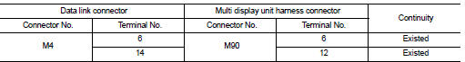
4. Check the continuity between the data link connector and the multi display
unit harness connector.
Is the inspection result normal? YES (Present error)>>Check CAN system type decision again.
YES (Past error)>>Error was detected in the main line between the the data link connector and the multi display unit.
NO >> Repair the main line between the data link connector and the multi display unit.
 Main line between DLC and A-bag circuit
Diagnosis Procedure
1.CHECK HARNESS CONTINUITY (OPEN CIRCUIT)
1. Turn the ignition switch OFF.
2. Disconnect the battery cable from the negative terminal.
3. Disconnect the BCM harness connector.
...
 ECM branch line circuit
Diagnosis Procedure
1.CHECK CONNECTOR
1. Turn the ignition switch OFF.
2. Disconnect the battery cable from the negative terminal.
3. Check the terminals and connectors of the ECM for damage, bend ...
Other materials:
How to use brightness control and display ON/OFF button
To change the display brightness, push the
button. Pushing the button again will
change the display to the day or the night display.
If no operation is performed within 5 seconds, the display will return to the
previous display.
Push and hold the button for more
than two seconds to turn t ...
NISSAN Intelligent Key battery replacement
CAUTION
Be extremely vigilant to ensure that children or pets cannot access, play with, or potentially swallow the small lithium battery and any of the disassembled plastic components of your Nissan Leaf key fob.
An improperly disposed lithium battery can cause significant ha ...
Unlock link function does not operate
Diagnosis Procedure
1.CHECK DRIVER SIDE OR PASSENGER SIDE DOOR SWITCH
Check driver side or passenger side door switch.
Refer to DLK-258, "Component Function Check".
Is the inspection result normal?
YES >> GO TO 2.
NO >> Repair or replace the malfunctioning parts.
...
