Nissan Juke Service and Repair Manual : Rear window defogger switch
With auto A/C
WITH AUTO A/C : Description
ÔÇó The rear window defogger is operated by turning the rear window defogger switch ON.
ÔÇó The indicator lamp in the rear window defogger switch illuminates when the rear window defogger is operating.
WITH AUTO A/C : Component Function Check
1.CHECK REAR WINDOW DEFOGGER SWITCH FUNCTION
Check that the indicator lamp of rear window defogger illuminates when rear window defogger switch ON.
Is the inspection result normal? YES >> Rear window defogger switch function is OK.
NO >> Refer to DEF-26, "WITH AUTO A/C : Diagnosis Procedure"
WITH AUTO A/C : Diagnosis Procedure
1.CHECK MULTI DISPLAY UNIT (REAR WINDOW DEFOGGER SWITCH)
Does multi display unit (rear window defogger switch) operate normally? ÔÇó Auto A/C (4WD models). Refer to HAC-29, "Description".
ÔÇó Auto A/C (2WD models). Refer to HAC-121, "Description".
Is the inspection result normal? YES >> INSPECTION END NO >> Replace multi display unit (rear window defogger switch).
Without auto A/C
WITHOUT AUTO A/C : Description
ÔÇó The rear window defogger is operated by turning the rear window defogger switch ON.
ÔÇó The indicator lamp in the rear window defogger switch illuminates when the rear window defogger is operating.
WITHOUT AUTO A/C : Component Function Check
1.CHECK FUNCTION
Check (REAR DEF SW) in BCM ÔÇťDATA MONITORÔÇŁmode using CONSULT-III when rear window defogger switch is ON.
Is the inspection result normal? YES >> Rear window defogger switch function is OK.
NO >> Refer to DEF-26, "WITHOUT AUTO A/C : Diagnosis Procedure"
WITHOUT AUTO A/C : Diagnosis Procedure
1.CHECK BCM OUTPUT SIGNAL
1. Turn ignition switch OFF.
2. Disconnect A/C control connector.
3. Check voltage between A/C control harness connector and ground.
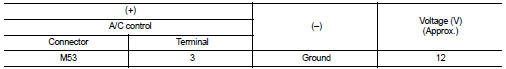
Is the inspection result normal? YES >> GO TO 3.
NO >> GO TO 2.
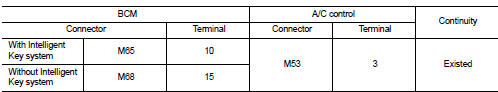
2.CHECK REAR WINDOW DEFOGGER SWITCH CIRCUIT
1. Disconnect BCM connector.
2. Check continuity between BCM harness connector and A/C control harness connector.
3. Check continuity between BCM harness connector and ground.
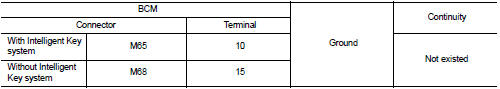
Is the inspection result normal? YES >> Replace BCM. Refer to BCS-93, "Removal and Installation" (With Intelligent Key system) or BCS- 161, "Removal and Installation" (Without Intelligent Key system).
NO >> Repair or replace harness.
3.CHECK GROUND CIRCUIT
Check continuity between A/C control harness connector and ground.
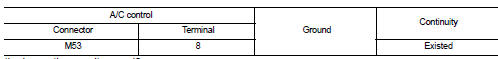
Is the inspection result normal? YES >> GO TO 4.
NO >> Repair or replace harness.
4.CHECK REAR WINDOW DEFOGGER SWITCH
Refer to DEF-27, "WITHOUT AUTO A/C : Component Inspection".
Is the inspection result normal? YES >> GO TO 5.
NO >> Replace A/C control. Refer to HAC-239, "Removal and Installation" (4WD models) or HAC-304, "Removal and Installation" (2WD models).
5.CHECK INTERMITTENT INCIDENT
Refer to GI-42, "Intermittent Incident".
Is the inspection result normal? >> INSPECTION END
WITHOUT AUTO A/C : Component Inspection
1.CHECK REAR WINDOW DEFOGGER SWITCH
1. Turn ignition switch OFF.
2. Disconnect A/C control connector.
3. Check continuity between A/C control terminals.
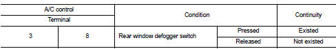
Is the inspection result normal? YES >> INSPECTION END
NO >> Replace A/C control. Refer to HAC-239, "Removal and Installation" (4WD models) or HAC-304, "Removal and Installation" (2WD models).
Without A/C
WITHOUT A/C : Description
ÔÇó The rear window defogger is operated by turning the rear window defogger switch ON.
ÔÇó The indicator lamp in the rear window defogger switch illuminates when the rear window defogger is operating.
WITHOUT A/C : Component Function Check
1.CHECK FUNCTION
Check (REAR DEF SW) in BCM ÔÇťDATA MONITORÔÇŁmode using CONSULT-III when rear window defogger switch is ON.
Is the inspection result normal? YES >> Rear window defogger switch function is OK.
NO >> Refer to DEF-28, "WITHOUT A/C : Diagnosis Procedure"
WITHOUT A/C : Diagnosis Procedure
1.CHECK BCM OUTPUT SIGNAL
1. Turn ignition switch OFF.
2. Disconnect heater control connector.
3. Check voltage between heater control harness connector and groun
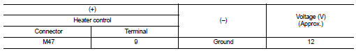
Is the inspection result normal? YES >> GO TO 3.
NO >> GO TO 2.
2.CHECK REAR WINDOW DEFOGGER SWITCH CIRCUIT
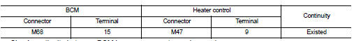
1. Disconnect BCM connector.
2. Check continuity between BCM harness connector and heater control harness connector.
3. Check continuity between BCM harness connector and groun
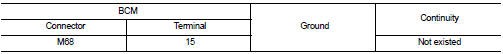
Is the inspection result normal?
YES >> Replace BCM. Refer to BCS-161, "Removal and Installation".
NO >> Repair or replace harness.
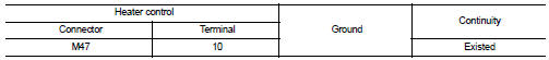
3.CHECK GROUND CIRCUIT
Check continuity between heater control harness connector and ground.
Is the inspection result normal? YES >> GO TO 4.
NO >> Repair or replace harness.
4.CHECK REAR WINDOW DEFOGGER SWITCH
Refer to DEF-29, "WITHOUT A/C : Component Inspection".
Is the inspection result normal? YES >> GO TO 5.
NO >> Replace heater control. Refer to HAC-331, "Removal and Installation".
5.CHECK INTERMITTENT INCIDENT
Refer to GI-42, "Intermittent Incident".
Is the inspection result normal? >> INSPECTION END
WITHOUT A/C : Component Inspection
1.CHECK REAR WINDOW DEFOGGER SWITCH
1. Turn ignition switch OFF.
2. Disconnect heater control connector.
3. Check continuity between heater control terminals.
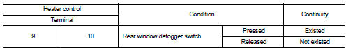
Is the inspection result normal? YES >> INSPECTION END
NO >> Replace heater control. Refer to HAC-331, "Removal and Installation".

 Rear window defogger relay
Description
The rear window defogger is operated by turning the rear window defogger
switch ON.
Component Function Check
1.CHECK FUNCTION
1. Perform IPDM E/R Active Test (ÔÇťREAR DEFOGGERÔÇŁ) us ...
Other materials:
B2099 ignition relay off stuck
Description
ÔÇó IPDM E/R operates the ignition relay when it receives an ignition switch ON
signal from BCM via CAN communication.
ÔÇó Turn the ignition relay OFF by pressing the push-button ignition switch once
when the vehicle speed is 4 km/
h (2.5 MPH) or less.
ÔÇó Turn the ignition relay ...
For frontal collision : When SRS is activated in a collision
CAUTION:
Due to varying models and option levels, not all parts listed in the chart below
apply to all vehicles.
WORK PROCEDURE
1. Before performing any of the following steps, ensure that all vehicle body
and structural repairs have been
completed.
2. Replace the diagnosis sensor unit.
...
System
Relay control system
RELAY CONTROL SYSTEM : System Diagram
*1: Except for MR16DDT engine models
*2: For MR16DDT engine models
RELAY CONTROL SYSTEM : System Description
IPDM E/R activates the internal control circuit to perform the relay ON-OFF
control according to the input signals
from va ...
