Nissan Juke Service and Repair Manual : P158A ECM
DTC Logic
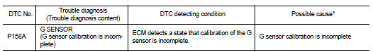
*: Since this DTC is detected when G sensor calibration is incomplete, there is not replacement parts.
1.PRECONDITIONING
If DTC Confirmation Procedure has been previously conducted, always perform the following procedure before conducting the next test.
1. Turn ignition switch OFF and wait at least 10 seconds.
2. Turn ignition switch ON.
3. Turn ignition switch OFF and wait at least 10 seconds.
>> GO TO 2.
2.PERFORM DTC CONFIRMATION PROCEDURE
1. Turn ignition switch ON.
2. Check DTC.
Is DTC detected? YES >> Proceed to EC-354, "Diagnosis Procedure".
NO >> INSPECTION END
Diagnosis Procedure
1.PERFORM CALIBRATION OF G SENSOR
Perform calibration of G sensor. Refer to EC-138, "Work Procedure".
>> INSPECTION END
 P1574 ASCD vehicle speed sensor
Description
The ECM receives two vehicle speed sensor signals via CAN communication line.
One is sent from combination
meter, and the other is from TCM (Transmission control module). The ECM uses ...
 P159A, P159C, P159D G sensor
For M/T models : DTC Logic
DTC DETECTION LOGIC
DTC CONFIRMATION PROCEDURE
1.PRECONDITIONING
If DTC Confirmation Procedure has been previously conducted, always perform
the following procedure
...
Other materials:
Precaution for On Board Diagnosis (OBD) System of CVT and Engine
The ECM has an on board diagnostic system. It will light up the malfunction
indicator (MI) to warn the driver of
a malfunction causing emission deterioration.
CAUTION:
• Be sure to turn the ignition switch OFF and disconnect the battery cable from
the negative terminal
before any repair ...
Exterior lighting system symptoms
Without daytime running light system
WITHOUT DAYTIME RUNNING LIGHT SYSTEM : Symptom Table
CAUTION:
Perform the self-diagnosis with CONSULT-III before the symptom diagnosis.
Perform the trouble diagnosis
if any DTC is detected.
With daytime running light system
WITH DAYTIME RUNNING LIGHT ...
Magnet clutch
Component Function Check
1.CHECK MAGNET CLUTCH OPERATION
Perform auto active test of IPDM E/R. Refer to PCS-12, "Diagnosis
Description" (with Intelligent Key) or PCS-
43, "Diagnosis Description" (without Intelligent Key).
Does it operate normally?
YES >> INSPECTION ...
