Nissan Juke Service and Repair Manual : Power supply and ground circuit
Diagnosis Procedure
1.CHECK FUSES AND FUSIBLE LINK
Check that the following IPDM E/R fuses or fusible links are not blown.
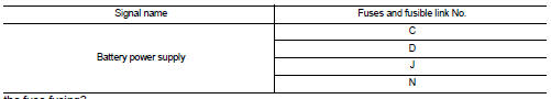
Is the fuse fusing? YES >> Replace the blown fuse or fusible link after repairing the affected circuit if a fuse or fusible link is blown.
NO >> GO TO 2.
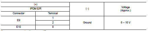
2.CHECK POWER SUPPLY CIRCUIT
1. Turn the ignition switch OFF.
2. Disconnect IPDM E/R connector.
3. Check voltage between IPDM E/R harness connector and the ground.
Is the measurement value normal? YES >> GO TO 3.
NO >> Repair the harness or connector.
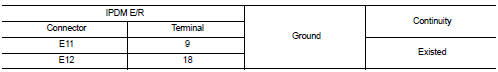
3.CHECK GROUND CIRCUIT
Check continuity between IPDM E/R harness connectors and the ground.
Does continuity exist? YES >> INSPECTION END
NO >> Repair the harness or connector.
 B2099 ignition relay off stuck
Description
The ignition relay integrated in IPDM E/R is operated with ignition switch ON
signal from the ignition switch.
DTC Logic
DTC DETECTION LOGIC
NOTE:
When IPDM E/R power supply volta ...
 Removal and installation
IPDM E/R
Exploded View
1. IPDM E/R cover A
2. IPDM E/R
3. IPDM E/R cover B
Removal and Installation
IPDM E/R integrated relays are not serviceable parts, and must not be removed
from the un ...
Other materials:
B26F8 BCM
DTC Logic
DTC DETECTION LOGIC
NOTE:
DTC B26F8 can be detected even though the related circuit is not used in this
vehicle.
DTC CONFIRMATION PROCEDURE
1.PERFORM DTC CONFIRMATION PROCEDURE
1. Turn ignition switch ON and wait 1 second.
2. Check DTC in “Self Diagnostic Result” mode of “ ...
Compressor dose dot operate
Description
SYMPTOM
Compressor dose not operate.
Diagnosis Procedure
NOTE:
• Perform self-diagnoses with CONSULT-III before performing symptom diagnosis.
If any DTC is detected,
perform the corresponding diagnosis.
• Check that refrigerant is enclosed in cooler cycle normally. If refrig ...
B1177 lap Pre-tensioner RH
DTC Logic
DTC CONFIRMATION PROCEDURE
1.CHECK SELF-DIAGNOSTIC RESULT
With CONSULT-III
1. Turn ignition switch ON.
2. Perform “Self Diagnostic Result” mode of “AIR BAG” using CONSULT-III.
Without CONSULT-III
1. Turn ignition switch ON.
2. Check the air bag warning lamp status. Refe ...
