Nissan Juke Service and Repair Manual : Removal and installation
IPDM E/R
Exploded View
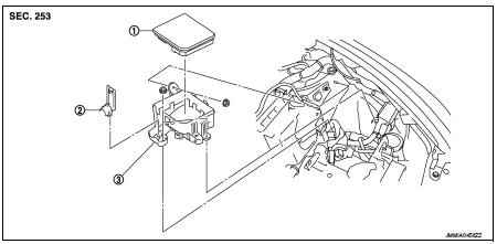
1. IPDM E/R cover A
2. IPDM E/R
3. IPDM E/R cover B
Removal and Installation
IPDM E/R integrated relays are not serviceable parts, and must not be removed from the unit.
REMOVAL
1. Remove battery.
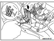
2. Press and expand pawls (A) on lateral side of IPDM E/R cover and remove IPDM E/R (1) from IPDM E/R cover B (2).
3. Disconnect the harness connector and then remove the IPDM E/R.
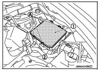
4. Remove IPDM E/R cover B mounting nuts (A).
5. Insert a flat-bladed screwdriver between IPDM E/R cover A (1) and IPDM E/R cover B (2), disengage pawls, and remove IPDM E/R cover A.
6. Remove IPDM E/R cover B.
INSTALLATION
Install in the reverse order of removal.
 Power supply and ground circuit
Diagnosis Procedure
1.CHECK FUSES AND FUSIBLE LINK
Check that the following IPDM E/R fuses or fusible links are not blown.
Is the fuse fusing?
YES >> Replace the blown fuse or fusible link ...

Other materials:
Headlamp aiming adjustment
LHD
LHD : Description
PREPARATION BEFORE ADJUSTING
NOTE:
• For details, refer to the regulations in your own country.
• Perform aiming if the vehicle front body has been repaired and/or the headlamp
assembly has been
replaced.
Before performing aiming adjustment, check the following.
...
How to select piston and bearing
Description
• The identification grade stamped on each part is the grade for the
dimension measured in new condition. This grade cannot apply to reused parts.
• For reused or repaired parts, measure the dimension accurately. Determine the
grade by comparing the
measurement with the valu ...
Magnet clutch
Component Function Check
1.CHECK MAGNET CLUTCH OPERATION
Perform auto active test of IPDM E/R. Refer to PCS-12, "Diagnosis
Description" (with Intelligent Key) or PCS-
43, "Diagnosis Description" (without Intelligent Key).
Does it operate normally?
YES >> INSPECTION ...
