Nissan Juke Service and Repair Manual : Magnet clutch
Component Function Check
1.CHECK MAGNET CLUTCH OPERATION
Perform auto active test of IPDM E/R. Refer to PCS-12, "Diagnosis Description" (with Intelligent Key) or PCS- 43, "Diagnosis Description" (without Intelligent Key).
Does it operate normally? YES >> INSPECTION END
NO >> Refer to HAC-83, "Diagnosis Procedure".
Diagnosis Procedure
1.CHECK FUSE
1. Turn ignition switch OFF.
2. Check 10A fuse (No. 49, located in IPDM E/R).
NOTE
:
Refer to PG-25, "Fuse, Connector and Terminal Arrangement".
Is the inspection result normal? YES >> GO TO 2.
NO >> Replace the blown fuse after repairing the affected circuit if a fuse is blown.
2.CHECK MAGNET CLUTCH
1. Disconnect compressor connector.
2. Directly apply battery voltage to the magnet clutch. Check for operation visually and by sound.
Does it operate normally? YES >> GO TO 3.
NO >> Replace magnet clutch. Refer to HA-88, "MAGNET CLUTCH : Removal and Installation of Compressor Clutch".
3.CHECK MAGNET CLUTCH POWER SUPPLY CIRCUIT FOR OPEN
1. Disconnect IPDM E/R connector.
2. Check continuity between IPDM E/R harness connector and compressor harness connector.
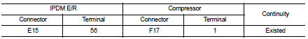
Is the inspection result normal? YES >> Replace IPDM E/R. Refer to PCS-34, "Removal and Installation" (with Intelligent Key) or PCS-63, "Removal and Installation" (without Intelligent Key).
NO >> Repair harness or connector.
 Blower motor
Diagnosis Procedure
1.CHECK FUSE
1. Turn ignition switch OFF.
2. Check following fuses.
- 10A fuse [No. 15, located in fuse block (J/B)]
- 15A fuses [Nos. 14 and 16, located in fuse block (J/B) ...

Other materials:
ECU diagnosis information
IPDM E/R
Reference Value
VALUES ON THE DIAGNOSIS TOOL
TERMINAL LAYOUT
PHYSICAL VALUES
*1: MR16DDT engine models
*2: Except MR16DDT engine models
*3: CVT models
*4: M/T models
*5: With daytime running light system
*6: Without daytime running light system
*7: K9K engine models ...
Vehicle-to-vehicle distance control mode limitations
WARNING
Below are the critical operational limitations for the Intelligent Cruise Control (ICC) system in your Nissan Leaf. Operating the vehicle without strict adherence to these guidelines could result in a loss of control, leading to serious injury or death.
The ICC system is ...
Wiring diagram
NISSAN DYNAMIC CONTROL SYSTEM
Wiring Diagram
For connector terminal arrangements, harness layouts, and alphabets in a
(option abbreviation; if not
described in wiring diagram), refer to GI-12, "Connector Information/Explanation
of Option Abbreviation".
...
