Nissan Juke Service and Repair Manual : P1864 input speed signal
DTC Logic
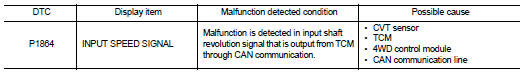
DTC DETECTION LOGIC
DTC CONFIRMATION PROCEDURE
1.PRECONDITIONING
If “DTC CONFIRMATION PROCEDURE” has been previously conducted, always turn ignition switch OFF and wait at least 10 seconds before conducting the next test.
>> GO TO 2.
2.DTC REPRODUCTION PROCEDURE
 With CONSULT-III
1. Start the engine and drive at 30 km/h (19 MPH) or more for approximately 1minute.
2. Perform self-diagnosis for “ALL MODE AWD/4WD”.
Is DTC “P1864” detected? YES >> Proceed to diagnosis procedure. Refer to DLN-74, "Diagnosis Procedure".
NO >> INSPECTION END
Diagnosis Procedure
1.PERFORM TCM SELF-DIAGNOSIS
With CONSULT-III
Perform self-diagnosis for “TRANSMISSION”.
Is any DTCs detected? YES >> Check the DTC. Refer to TM-171, "DTC Index".
NO >> GO TO 2.
2.ERASE SELF-DIAGNOSTIC RESULT
With CONSULT-III
1. Erase self-diagnostic results for “ALL MODE AWD/4WD”.
2. Start the engine and drive vehicle at 30 km/h (19 MPH) or more.
3. Check that A/T CHECK indictor lamp turns OFF.
Does A/T CHECK indicator lamp turn OFF? YES >> GO TO 3.
NO >> Refer to TM-259, "Symptom Table".
3.CHECK TERMINALS AND HARNESS CONNECTORS
Check 4WD control module pin terminals for damage or loose connection with harness connector.
Is inspection result normal? YES >> After turning the ignition switch OFF, perform DTC confirmation procedure again. When DTC “P1864” is detected, Replace 4WD control module. Refer to DLN-91, "Removal and Installation".
NO >> Repair or replace error-detected parts.
 P1840 output speed signal
DTC Logic
DTC DETECTION LOGIC
DTC CONFIRMATION PROCEDURE
1.PRECONDITIONING
If “DTC CONFIRMATION PROCEDURE” has been previously conducted, always turn
ignition switch OFF and
wait at least ...
 P1865 gear ratio signal
DTC Logic
DTC DETECTION LOGIC
DTC CONFIRMATION PROCEDURE
1.PRECONDITIONING
If “DTC CONFIRMATION PROCEDURE” has been previously conducted, always turn
ignition switch OFF and
wait at least ...
Other materials:
Precaution for Brake System
WARNING:
Clean any dust from the front brake and rear brake with a vacuum dust collector.
Never blow with compressed
air.
• Brake fluid use refer to MA-13, "Fluids and Lubricants".
• Never reuse drained brake fluid.
• Never spill or splash brake fluid on painted surfaces. Brak ...
Compressor dose dot operate
Description
SYMPTOM
Compressor dose not operate.
Diagnosis Procedure
NOTE:
• Perform self-diagnosis with CONSULT-III before performing symptom diagnosis.
If any malfunction result or
DTC is detected, perform the corresponding diagnosis.
• Check that refrigerant is enclosed in cooler cyc ...
Removal and installation
ALTERNATOR
HR16DE
HR16DE : Exploded View
REMOVAL
1. Alternator bracket mounting bolt
2. Alternator bracket
3. Alternator mounting bolt
4. Alternator
5. “B” terminal harness
6. “B” terminal nut
7. Alternator connector
: N·m (kg-m, ft-lb)
DISASSEMBLY
Type: A002TJ1291ZE
1 ...
