Nissan Juke Service and Repair Manual : P1865 gear ratio signal
DTC Logic
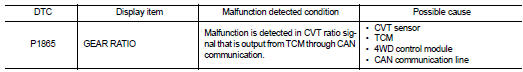
DTC DETECTION LOGIC
DTC CONFIRMATION PROCEDURE
1.PRECONDITIONING
If ŌĆ£DTC CONFIRMATION PROCEDUREŌĆØ has been previously conducted, always turn ignition switch OFF and wait at least 10 seconds before conducting the next test.
>> GO TO 2.
2.DTC REPRODUCTION PROCEDURE
 With CONSULT-III
1. Start the engine and drive at 30 km/h (19 MPH) or more for approximately 1minute.
2. Perform self-diagnosis for ŌĆ£ALL MODE AWD/4WDŌĆØ.
Is DTC ŌĆ£P1865ŌĆØ detected? YES >> Proceed to diagnosis procedure. Refer to DLN-75, "Diagnosis Procedure".
NO >> INSPECTION END
Diagnosis Procedure
1.PERFORM TCM SELF-DIAGNOSIS
With CONSULT-III
Perform self-diagnosis for ŌĆ£TRANSMISSIONŌĆØ.
Is any DTCs detected? YES >> Check the DTC. Refer to TM-171, "DTC Index".
NO >> GO TO 2.
2.ERASE SELF-DIAGNOSTIC RESULT
With CONSULT-III
1. Erase self-diagnostic results for ŌĆ£ALL MODE AWD/4WDŌĆØ.
2. Start the engine and drive vehicle at 30 km/h (19 MPH) or more.
3. Check that A/T CHECK indictor lamp turns OFF.
Does A/T CHECK indicator lamp turn OFF? YES >> GO TO 3.
NO >> Refer to TM-259, "Symptom Table".
3.CHECK TERMINALS AND HARNESS CONNECTORS
Check 4WD control module pin terminals for damage or loose connection with harness connector.
Is inspection result normal? YES >> After turning the ignition switch OFF, perform DTC confirmation procedure again. When DTC ŌĆ£P1865ŌĆØ is detected, Replace 4WD control module. Refer to DLN-91, "Removal and Installation".
NO >> Repair or replace error-detected parts.
 P1864 input speed signal
DTC Logic
DTC DETECTION LOGIC
DTC CONFIRMATION PROCEDURE
1.PRECONDITIONING
If ŌĆ£DTC CONFIRMATION PROCEDUREŌĆØ has been previously conducted, always turn
ignition switch OFF and
wait at least ...
 U1000 can comm circuit
Description
CAN (Controller Area Network) is a serial communication line for real time
application. It is an on-vehicle multiplex
communication line with high data communication speed and excellen ...
Other materials:
Precaution Necessary for Steering Wheel Rotation after Battery Disconnect
NOTE:
ŌĆó Before removing and installing any control units, first turn the ignition
switch to the LOCK position, then disconnect
both battery cables.
ŌĆó After finishing work, confirm that all control unit connectors are connected
properly, then re-connect both
battery cables.
ŌĆó Always us ...
P1197 out of gas
Description
This diagnosis result is detected when the fuel level of the fuel tank is
extremely low and the engine does not
run normally.
DTC Logic
DTC DETECTION LOGIC
DTC CONFIRMATION PROCEDURE
1.PRECONDITIONING
1. Turn ignition switch OFF and wait at least 10 seconds.
2. Turn ignition ...
Dynamic driver assistance switch
(for vehicles without ProPILOT Assist)
The physical dynamic driver assistance switch allows the operator to temporarily activate or deactivate the advanced Intelligent Lane Intervention (I-LI) and Intelligent Blind Spot Intervention (I-BSI) safety systems, assuming these safety features have already been enabled wit ...
