Nissan Juke Service and Repair Manual : Cylinder block
Disassembly and Assembly
PREPARING USED ENGINE
The engine should be cleaned and drained (oil and water).
Leave on the used engine or include in the return box:
• Oil filter
• Oil pressure switch
• Water pump
• Fuel injection pump
• Rail
• Injectors
• Glow plugs
• Oil level gauge
• Vacuum pump
• Flywheel
Remember to remove:
• All coolant pipes
• Exhaust manifold
• Alternator
• Power steering pump
• A/C compressor
• Alternator bracket
• Oil level sensor
• Cylinder head coolant outlet unit
The used engine should be secured to the base under the same conditions as
the overhauled engine:
• Plastic plugs and covers fitted
• Cardboard cover over the assembly
DISASSEMBLY
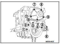
REMOVING THE UPPER ENGINE
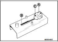
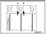
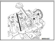
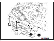
1. Remove the upper timing cover by unclipping the two tabs (A).
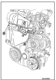
2. Remove the lower timing cover by unclipping the three tabs (B) and pulling out the plastic bolt (C).
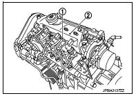
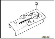
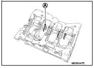
3. Remove the cylinder head suspended mounting bracket and high pressure pump position sensor.
4. Remove the TDC pin cap.
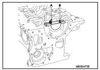
POSITIONING THE BELT AT THE TIMING POINT
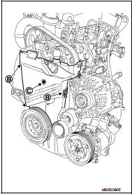
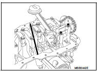
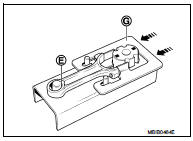
1. Rotate the crankshaft clockwise, until the position (A) of the camshaft pulley becomes opposite of the position (B) on the cylinder head.
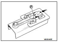
![2. Insert TDC set pin [SST: KV 113B0110 (Mot. 1430)] (A) into the](images/books/335/7/index.1.jpg)
2. Insert TDC set pin [SST: KV 113B0110 (Mot. 1430)] (A) into the camshaft pulley and cylinder head.
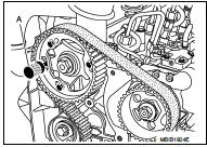
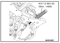
3. Screw in the Tool KV113B0130 (Mot. 1489).
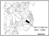
4. Turn the engine clockwise (timing side) until the crankshaft reaches the Tool KV113B0130 (Mot. 1489).
5. The Tool KV113B110 (Mot. 1430) (A) must engage in the camshaft pulley and cylinder head holes.
6. Remove Tool KV113B0130 (Mot. 1489).

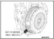
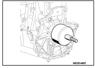
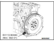
7. Install the Tool KV113B0060 (Mot. 582-01).

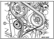
8. Remove the crankshaft pulley (1).

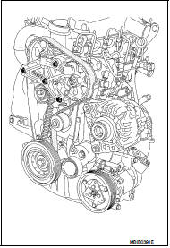
9. Slacken the timing belt by loosening the bolt of the tensioner (1), then remove the timing belt.
10. Remove the timing belt tensioner and inner timing cover.
11. Remove air cleaner case. Refer to EM-278.
12. Remove the turbocharger oil supply pipe (A) on the cylinder head side.

13. Remove the turbocharger oil supply pipe on the turbocharger side, nuts (A) and the torx bolt of the turbocharger flange, and turbocharger oil outlet hose (1).

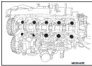
14. Unclip the fuel return pipe from the cylinder head cover at the fuel spill tube (1), then remove the rocker cover (2).
15. Remove the oil level gauge guide and cylinder head.
CLEANING
• It is very important not to scratch the gasket faces of any aluminium components.
• Use suitable tool to dissolve any part of the seal which remains stuck to the metal surface.
• Apply the dissolving product to the part to be cleaned, wait approximately 10 minutes, then remove it using a wooden spatula.
• Wear gloves while carrying out this operation.
• Do not allow this dissolving product to drip on to the paintwork.
• Great care should be taken when performing this operation, to prevent foreign objects from entering the pipes taking oil under pressure to the camshafts (pipes in both the cylinder head and its cover) and the oil return pipes.
• Failure to follow these instructions could lead to the blocking of the oilways, resulting in rapid and serious damage to the engine.
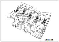
DISASSEMBLY OF THE BOTTOM ENGINE
1. Install the Tool KV113B0060 (Mot. 582-01).
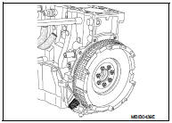
2. Remove the clutch housing.
3. Remove the flywheel.
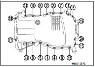
4. Remove the oil pan bolt in reverse order as shown.
5. Remove the baffle plate.
6. Remove the oil level sensor.
7. Remove the oil pump.
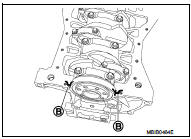
8. Remove the rear oil seal retainer.
9. Remove the water pump.
10. Remove the oil pump chain.
11. Remove the oil pump drive sprocket.
WARNING:
Never use a sharp point to mark the bearing caps in relation
to their connecting rods to avoid starting a crack in the rod.
Use a permanent marker pen.
12. Remove the big end cap bolts and the connecting rod/piston assemblies.
NOTE
:
It is essential to mark the position of the main bearing cap,
as the category may be different for each bearing.
13. Remove the main bearing caps.
14. Remove the crankshaft.
15. Remove the oil pressure switch, the knock sensor and oil filter bracket connecting bolt.

16. Remove the oil cooler connecting bolt.

REMOVING THE PISTON PINS
NOTE
:
It is imperative to mark the connecting rod to match it to its piston, because
the piston height classes
in the same engine may be different (see Technical Specifications section).
To remove the piston pin, remove the snap ring using a screwdriver, then release the pin.
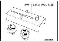
CONNECTING ROD BEARING
• The connecting rod bearing are installed using Tool KV113B0140 (Mot. 1492) and Tool KV113B0150 (Mot. 1492-03).
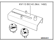
ON THE CONNECTING ROD BODY
1. Slide the connecting rod bearing support (A) of Tool KV113B0150 [Mot. 1492-03 (positioning the engraved mark (B) as shown in the figure)] into the groove (C) of the base of Tool KV113B0140 (Mot. 1492).
2. Install the guide (D) of Tool KV113B0150 (Mot. 1492-03) onto the base (as shown in the figure).
3. Lay the body of the connecting rod on the base of the tool (as shown in the diagram). Check that the lower part (E) of the small end is touching the centering pin and push the guide (G) in the direction of the arrow.
4. Lay the connecting rod bearing [with a width of 20.625 mm (0.8120 in)] (F) on the connecting rod bearing support, then push it in the direction of the arrow (as shown in the figure).
5. Bring the connecting rod support up against the base of the connecting rod body.
6. Remove the connecting rod body support and repeat the operation for the remaining connecting rod bodies.
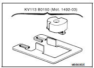
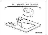
ON THE CONNECTING ROD CAP
1. Position the connecting rod bearing support either on the engraved mark (C) if the width of the connecting rod bearing is equal to 20.625 mm (0.8120 in).
2. Position the connecting rod bearing support either on the engraved mark (D) if the width of the connecting rod bearing is equal to 17.625 mm (0.6939 in).
3. Install the connecting rod cap as shown in the figure.
4. Push the guide (in the direction of the arrow) until the connecting rod cap is in contact with the pins (I) on the base of the tool.

5. Install the connecting rod bearing (H) on the bearing support, then push it in the direction of the arrow (as shown in the figure).
6. Bring the connecting rod bearing support up against the base of the connecting rod cap.
7. Remove the connecting rod bearing support and repeat the operation for the remaining connecting rod caps.
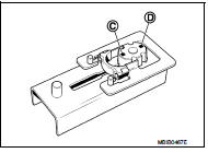
REPLACEMENT OF THE OIL JETS
RemovalREPLACEMENT OF THE OIL JETS Removal 1. To remove the oil jets (A), they must be drilled with a 7 mm (0.28 in) diameter drill. This is necessary in order to remove the spring stop (B) and the spring (C).
1. To remove the oil jets (A), they must be drilled with a 7 mm (0.28 in) diameter drill. This is necessary in order to remove the spring stop (B) and the spring (C).
NOTE:
Do not remove the ball (D) to prevent from entering the
cooling circuit.
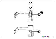
2. Remove the chippings and spring using a suitable brush.
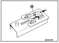
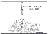
3. Screw Tool KV113B0120 (Mot. 1485-01) in the drilled out jets using a 6 mm (0.24 in) Allen key which must slide into the tool.
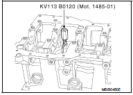
4. Screw Tool KV113B0020 (Emb. 880) onto KV113B0120 (Mot.
1485-01) and remove the oil jet.
ASSEMBLY
INSTALLATION OF OIL JETS
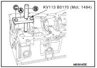
Installation of The Oil Jets For No.1 and No.3 Cylinders 1. Install plate (A) of Tool KV113B0170 (Mot. 1494) onto the cylinder block (as shown in the figure) without tightening the two bolts (C).
2. Position the guide rod (B) in the plate (A) and the end of the guide rod in the hole of the oil jet to center the plate (A).
3. Tighten the two bolts (C).
4. Remove the guide rod.
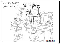
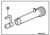
5. Install the push rod instead of the guide rod, then insert the oil jet into the push rod.
NOTE:
Check that the oil jet is correctly oriented with the end of
the jet (D) directed towards the center of the cylinder.

6. The oil jets must be installed using Tool KV113B0170 (Mot. 1494).
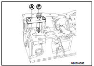
7. With a hammer, tap the push rod until the shoulder (E) of the push rod comes into contact with the plate (A).
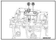
Installation of The Oil Jets For No.2 and No.4 Cylinders 1. Fit plate (A) of Tool KV113B0170 (Mot. 1494) onto the cylinder block (as shown in the figure) without tightening the two bolts (C).
2. Position the guide rod (B) in the plate (A) and the end of the guide rod in the hole of the oil jet to center the plate (A).
3. Tighten the two bolts (C).
4. Remove the guide rod.
5. Position the push rod instead of the guide rod, then insert the oil jet into the push rod.
NOTE:
Check that the oil jet is correctly oriented with the end of
the jet (D) directed towards the center of the cylinder
.
6. With a hammer, tap the push rod until the shoulder (E) of the push rod comes into contact with the plate (A).
Orientation Of The Oil Jets (See Diagram Below) • Clean the cylinder block and crankshaft by passing a wire through the lubrication channels.
INSTALLATION OF MAIN BEARING
1. Position the grooved main bearings on the cylinder block.
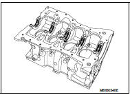
2. Install the smooth bearings on the bearing caps.
MAIN BEARING
• The engine is installed with main bearing without a locator notch.
1. The main bearings are installed on the cylinder block and on the bearings using Tool KV113B0160 (Mot. 1493-01).
2. For direction of installation on the cylinder block, install grooved main bearing on all the bearings
3. For direction of installation on the bearing caps, install nongrooved main bearing.
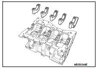
ON THE CYLINDER BLOCK
1. Position tool KV113B0160 (Mot. 1493-01) on the cylinder block.
2. Press at (A) until the bearing cap is touching at (B) with KV113B0160 (Mot. 1493-01).
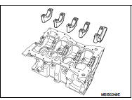
ON THE BEARING CAPS
1. Position Tool KV113B0160 (Mot. 1493-01) on the bearing cap.
2. Install the main bearing in Tool KV113B0160 (Mot. 1493-01), then press at (A) until the main bearing is touching at (B) with Tool KV113B0160 (Mot. 1493-01).
3. Oil the main bearing.
4. Install the crankshaft.
5. Install the lateral shims on bearing No. 3, putting the grooves on the crankshaft side.
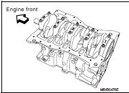
6. Install the main bearing caps on bearing cap No. 1 (these are numbered from 1 - 5 and these numbers should be positioned opposite the water pump), and tighten the bolts as follows: a. Tighten the bolts.
 : 25 N·m (2.6 kg-m, 18 ft-lb)
b. Turn the bolt 47 degrees ±± 6 degrees clockwise (angle tightening).
7. Check the lateral clearance of the crankshaft which should be
without wear on lateral shims: 0.045 - 0.252 mm (0.0018 -
0.0099 in)
8. Check the lateral clearance of the crankshaft which should be
with wear on the lateral shims: 0.045 - 0.852 mm (0.0018 -
0.0335 in)
INSTALLATION OF NO. 1 BEARING
1. Degrease the gasket faces (of the cylinder block and bearing No. 1). They should be clean, dry and free from grease (in particular, remove finger marks).
2. Lay two beads of liquid sealant with a width of 1 mm (0.04 in) on bearing No. 1 of the cylinder block.
Tighten the bolts of bearing cap No. 1, and tighten the bolts as follows: a. Tighten the bolts.
: 25 N·m (2.6 kg-m, 18 ft-lb)
b. Turn the bolt 47 degrees ±± 6 degrees clockwise (angle tightening).
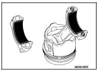
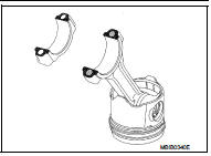
CONNECTING RODS / PISTON ASSEMBLY
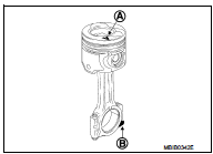
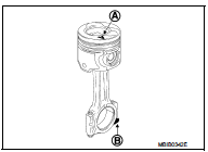
• The pistons have a mark engraved on their heads indicating the engine rear side.
1. Oil the piston pin.
2. Check that the piston pins rotate correctly in the new piston and in the matching connecting rod.
Direction Of Installation Of The Connecting Rod In Relation To The Piston • Point the mark (A) engraved on the top of the piston upwards and the flat (B) of the big end downwards as shown in the figure.
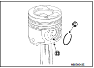
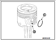
DIRECTION FOR INSTALLATION THE SNAP RINGS ON THE PISTON
• Position the opening (C) of the snap rings opposite the removal and fitting channel (D).
INSTALLATION OF THE SNAP RINGS
1. Rings set to their original adjustment must be free within their channels.
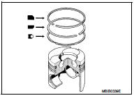
2. Ensure the snap rings are fitted the correct way, with the word TOP pointing upwards.
Orientation Of The Piston Rings In The Piston
1. Ensure the break in each piston ring is correctly oriented as shown in the figure.
2. Apply new engine oil to the pistons.
3. Install the connecting rod/piston assemblies into the cylinder block using the ring, being careful to fit them the right way round (mark towards the flywheel).
4. Install the connecting rods onto the oiled crankshaft pins of the crankshaft.
5. Install the connecting rod caps, ensuring they are correctly matched.
6. Tighten the big end cap bolts to a torque of 20 N·m (2.0 kg-m, 15 ft-lb), plus an angle tightening of 45°±6°.
: 20 N·m (2.0 kg-m, 15ft-lb)
7. Inspect that the big ends have the correct lateral clearance of 0.205 to 0.467 mm (0.0081 to 0.0184 in).
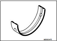
CONNECTING ROD BEARING
• The engine is installed with connecting rod bearing without a locator notch.
NOTE
:
The upper and lower connecting rod bearing are not the same
width.
Connecting rod bearing width: Upper bearing : 20.625 mm (0.8120 in) Lower bearing : 17.625 mm (0.6939 in)
• The connecting rod bearing are installed using Tool KV113B0140 (Mot. 1492) and Tool KV113B0150 (Mot. 1492-03).
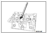
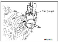
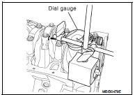
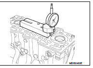
CHECKING PISTON PROTRUSION
1. Clean the piston head.
2. Turn the crankshaft one turn in its operating direction to bring piston No. 1 close to TDC.
3. Install Tool KV113B0050 (Mot. 252-01) (Commercial service tool) or equivalent tool on the piston.
4. Install Tool KV113B0040 (Mot. 251-01) (Commercial service tool) or equivalent tool equipped with a gauge on support plate KV113B0050 (Mot. 252-01) (Commercial service tool) or equivalent tool, and find TDC.
NOTE
:
All measurements must be carried out along the longitudinal
axis of the engine, in order to eliminate any errors due to tilting
of the piston.
WARNING:
The gauge follower must not be in the valve clearance.
5. Inspect the piston protrusion which must be 0.099 to 0.285 mm (0.0039 to 0.0112 in).
Height of the cylinder head:
H = 127 mm (5.00 in)
Gasket face bow:
Cylinder head : 0.05 mm (0.0020 in)
Cylinder block : 0.03 mm (0.0012 in)
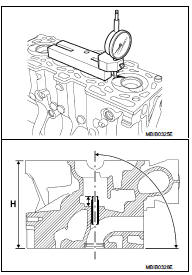
NO REGRINDING IS AUTHORIZED
Test the cylinder head to detect possible cracks using the cylinder head test container (comprising a tray and a kit suited to the cylinder head, plug, sealing plate and blanking plate).
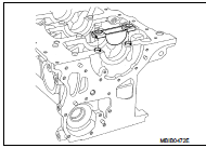
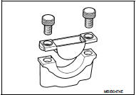
INSTALLATION OF REAR OIL SEAL RETAINER AND OIL PUMP
1. Tighten the knock sensor.
 : 20 N·m (2.0 kg-m, 15ft-lb)
2. Tighten the oil pressure sensor.
 : 25 N·m (2.6 kg-m, 18ft-lb)
3. Install the oil pump sprocket and chain.
 : 25 N·m (2.6 kg-m, 18ft-lb)
NOTE
:
The gasket faces (cylinder block, rear oil seal retainer and
water pump) must be clean, dry and free from grease (in
particular, remove finger marks).
The rear oil seal retainer should be applied with liquid gasket.
The bead (A) must be 1.5 to 2 mm (0.059 to 0.079 in) wide and be applied in accordance with the figure.
• Use Genuine Liquid Gasket or equivalent.
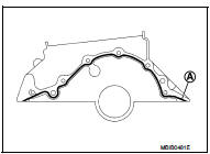
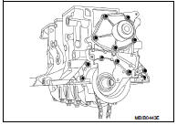
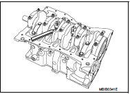
4. Install the rear oil seal retainer. Tighten bolts (No.1 to 6) as shown in the figure.
 : 12 N·m (1.2 kg-m, 9ft-lb)
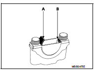
5. Put a new gasket to water pump face and install the water pump. Put a drop of locking sealant on the bolts (No.7 to 11) in the numerical order as shown in the figure.
 : 11 N·m (1.1 kg-m, 8ft-lb)
• Use Genuine thread locking sealant or equivalent.
NOTE:
The gasket faces (cylinder block and rear oil seal retainer)
must be clean, dry and free from grease (in particular,
remove finger marks).
6. Apply four beads (B) of liquid gasket, with a diameter of 5 mm (0.20 in).
7. Apply two drops (C) of liquid gasket, with a diameter of 7 mm (0.28 in) at the intersection of the rear oil seal retainer and the cylinder block.
• Use Genuine Liquid Gasket or equivalent.
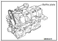
8. When installing the oil pan, ensure that the tabs (D) of the baffle plate are correctly positioned in the slots (E).
9. When installing the oil pan, ensure that the cylinder block and the oil pan are correctly aligned on the flywheel side, to prevent the clutch housing from being damaged when installing the transaxle.
10. Install the baffle plate.
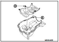
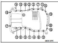
11. Install the oil pan, and tighten the bolts in the numerical order as shown in the figure
: 14 N·m (1.4 kg-m, 10ft-lb)
INSTALLATION OF THE CRANKSHAFT SEAL GASKETS
1. Crankshaft elastomer seal, timing side.
2. Screw the threaded rod (A) of Tool KV113B0220 (Mot. 1586) into the crankshaft.
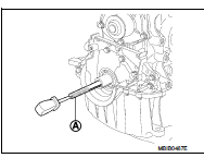
3. Position the spacer (B) of Tool KV113B0220 (Mot. 1586) on the crankshaft.
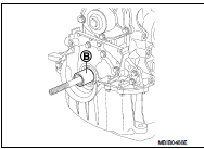
4. Install the protector complete with the seal onto the spacer, taking care not to touch the seal.
5. Install the cover (A) and the nut (B) (putting the threaded part (C) of the nut on the side away from the engine) of Tool KV113B0220 (Mot. 1586).
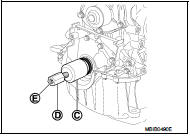
6. Tighten the nut until the cover touches the spacer.
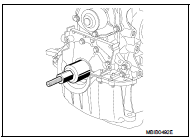
7. Remove the nut, the cover, the protector and the threaded rod.
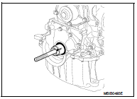
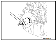
8. Crankshaft elastomer seal, flywheel side.
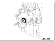
9. Install Tool KV113B0210 (Mot. 1585) on the crankshaft, securing it with bolts (F).
10. Put the protector complete with the seal on Tool KV113B0210 (Mot. 1585), being careful not to touch the seal.
11. Install the cover (G) and nut (H) (putting the threaded part (I) of the nut on the side away from the engine) of Tool KV113B0210 (Mot. 1585).
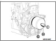
12. Tighten the nut until the cover touches the cylinder block.
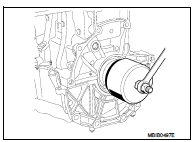
13. Remove the nut, the cover, the protector and the threaded rod.
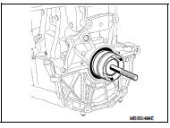
14. Install Tool KV113B0060 (Mot. 582-01) and tighten the new bolts.
 : 50 - 60 N·m (5.1 - 6.1 kg-m, 37
- 44 ft-lb)
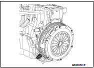
15. Install the clutch housing, tightening the bolts to the torque.
M6 bolt : 13 - 16 N·m
(1.3 - 1.6 kg-m, 10 - 12 ft-lb)
M7 bolt : 18 - 22 N·m
(1.8 - 2.2 kg-m, 13 - 16 ft-lb)
16. Remove Tool KV113B0060 (Mot. 582-01).
METHOD FOR INSTALLING THE OIL COOLER AND OIL FILTER
1. Install oil cooler. Refer to LU-37, "Exploded View".
2. Install oil filter. Refer to LU-35, "Exploded View".
Inspection
PISTON MARKING
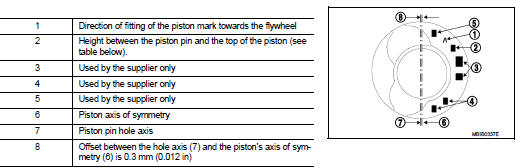
TABLE OF PISTON PIN HEIGHT
The tolerance on the piston pin heights is ±0.02 mm (±0.0008).
* The different piston pin heights are exclusively reserved for the engine assembly plant.
The service parts will only supply piston classes (height) L, M, N.
NOTE
:
• If the engine is installed with a K class piston, an L class piston must be
installed as a replacement.
• If the engine is installed with a P class piston, an N class piston must be installed as a replacement.
MEASURING THE PISTON DIAMETER
The piston diameter must be measured at height A = 56 mm (2.20 in).
Piston diameter : 75.933 - 75.947 mm (2.9895 -
2.9900 in)
Piston pin:
Length : 59.7 - 60.3 mm (2.350 - 2.374 in)
Outer diameter : 24.8 - 25.2 mm (0.976 - 0.992 in)
Inner diameter : 13.55 - 13.95 mm (0.5335 -
0.5492 in)

PISTON RING
Thickness:
Top ring : 1.97 - 1.99 mm (0.0776 - 0.0783 in)
2nd ring : 1.97 - 1.99 mm (0.0776 - 0.0783 in)
Oil ring : 2.47 - 2.49 mm (0.0972 - 0.0980 in)
The piston rings are supplied ready adjusted.

PISTON RING END GAP
Top ring : 0.20 - 0.35 mm (0.0079 - 0.0138 in) 2nd ring : 0.70 - 0.90 mm (0.0276 - 0.0354 in) Oil ring : 0.25 - 0.50 mm (0.0098 - 0.0197 in)
CONNECTING ROD
The connecting rod is of the detachable cap type.
WARNING:
• The bolts must be coated with engine oil under the heads and
on the threads when the connecting rods are installed in the
engine.
• The big end caps are positioned on the connecting rod by irregularities on the parting line.
• The occurrence of impacts or a foreign body between the body - cap mating surfaces will lead to rapid rupture of the connecting rod.
Lateral big end play : 0.205 - 0.467 mm (0.0081 -
0.0184 in)
Diametrical big end play : 0.035 - 0.045 mm (0.0014 -
0.0018 in)
Center distance between
the big end and small end
: 133.75 mm (5.2657 in)
Diameter of the big end : 47.610 - 47.628 mm (1.8744 -
1.8751 in)
Diameter of the small end
(without ring) : 27.24 - 27.26 mm (1.0724 -
1.0732 in)
(with ring) : 25.013 - 25.025 mm (0.9848 -
0.9852 in)
NOTE
:
The connecting rod small end rings cannot be replaced.
The maximum weight difference for the connecting rod, piston and piston pin assemblies for the same engine must be 0.245 N (25 g, 0.88 oz).
WARNING:
• To avoid initiating a crack in the connecting rod, Never use a
sharp point to mark the big end caps in relation to their connecting
rod.
• Use a permanent marker pen.
DIRECTION OF INSTALLATION OF THE CONNECTING ROD IN RELATION TO THE PISTON
• Point the mark (A) engraved on the top of the piston upwards and the machined flat (B) of the big end downwards as shown in the figure.
DIRECTION FOR INSTALLATION THE SNAP RINGS ON THE PISTON
• Position the opening (C) of the snap rings opposite of the removal and installation channel (D).
CRANKSHAFT
Number of main journals : 5 Crankshaft side clearance: Without wear on side shims : 0.045 - 0.252 mm (0.0018 - 0.0099 in) With wear on side shims : 0.045 - 0.852 mm (0.0018 - 0.0335 in) Crankshaft diametrical clearance: Journals : 0.027 - 0.054 mm (0.0011 - 0.0021 in) Crankshaft pins : 0.035 - 0.045 mm (0.0014 - 0.0018 in) Journal diameter: : 47.99 - 48.01 mm (1.8894 - 1.8902 in) Crankshaft pin diameter: : 43.96 - 43.98 mm (1.7307 - 1.7315 in)
• The lateral shims are located on bearing No. 3.
• No rectifications are allowed.
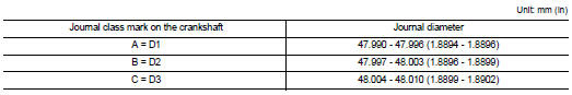
WORKING OUT THE CLASS OF MAIN BEARING (ORIGINAL FITMENT)
Marking (A) On The Crankshaft • Detail of the marking (A): Number of journals

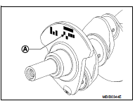
* Flywheel end.
Table Of Journal Diameter Classes
CYLINDER BLOCK
ENGINE IDENTIFICATION
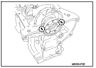
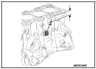
The diameters of the bearings (A) of the cylinder block are marked by a hole on the block (B) located above the oil filter.

ENGINE IDENTIFICATION
Identification is by means of an engraved plate on the cylinder block
which carries:
• A: engine type
• B: engine type approval letter
• D: code
• E: engine suffix
• F: engine serial number
• G: engine assembly plant

TABLE OF CYLINDER BLOCK MAIN BEARING HOUSING INNER DIAMETERS
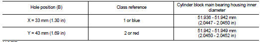
NOTE:
The marking zone includes:
• X - Y gives the diameter class of bearings A or B.
MATCHING THE MAIN BEARING
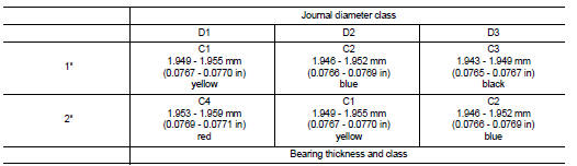
* Cylinder block main bearing diameter class.
NOTE
:
The service parts will only supply class C2 (blue).
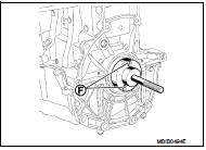
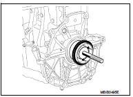
 Engine stand setting
Preparing the engine to be on the stand
Before the engine is mounted on the engine sub-attachment, the engine's
electrical harness must be removed
and the engine oil drained.
1. Remove the mult ...

Other materials:
I-FCW System operation
Vehicle ahead detection indicator
AEB with Pedestrian Detection system warning light
The I-FCW system is fully active when the Nissan Leaf is traveling at speeds above approximately 3 mph (5 km/h), ensuring protection during b ...
B1120 satellite sensor LH
DTC Logic
DTC DETECTION LOGIC
DTC CONFIRMATION PROCEDURE
1.CHECK SELF-DIAG RESULT
With CONSULT-III
1. Turn ignition switch ON.
2. Perform “Self Diagnostic Result” mode of “AIR BAG” using CONSULT-III.
Without CONSULT-III
1. Turn ignition switch ON.
2. Check the air bag warning la ...
Basic inspection
DIAGNOSIS AND REPAIR WORK FLOW
Work Flow
DETAILED FLOW
1.OBTAIN INFORMATION ABOUT SYMPTOM
Interview the customer to obtain as much malfunction information (conditions
and environment when the malfunction
occurred) as possible when the customer brings the vehicle in.
>> GO TO 2.
2. ...
