Nissan Juke Service and Repair Manual : P1705 TP sensor
Description
Electric throttle control actuator consists of throttle control motor, accelerator pedal position sensor, throttle position sensor etc. The actuator sends a signal to the ECM, and ECM sends the signal to TCM with CAN communication.
DTC Logic
DTC DETECTION LOGIC
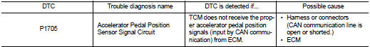
DTC CONFIRMATION PROCEDURE
NOTE
:
If ÔÇťDTC CONFIRMATION PROCEDUREÔÇŁ has been previously performed, always turn
ignition switch
OFF and wait at least 10 seconds before performing the next test.
After the repair, perform the following procedure to confirm the malfunction is eliminated.
1.CHECK DTC DETECTION
With CONSULT-III
1. Turn ignition switch ON.
2. Depress accelerator pedal fully and release it, then wait for 5 seconds.
3. Select ÔÇťSelf Diagnostic ResultsÔÇŁ in ÔÇťTRANSMISSIONÔÇŁ.
Is ÔÇťP1705ÔÇŁ detected? YES >> Go to TM-241, "Diagnosis Procedure".
NO >> Check intermittent incident. Refer to GI-42, "Intermittent Incident".
Diagnosis Procedure
1.CHECK INPUT SIGNAL
 With CONSULT-III
1. Turn ignition switch ON.
2. Select ÔÇťDATA MONITORÔÇŁ in ÔÇťTRANSMISSIONÔÇŁ.
3. Read out the value of ÔÇťACC PEDAL OPENÔÇŁ.

Is the inspection result normal? YES >> Check intermittent incident. Refer to GI-42, "Intermittent Incident".
NO >> GO TO 2.
2.CHECK DTC WITH ECM
 With CONSULT-III
1. Turn ignition switch ON.
2. Select ÔÇťSELF-DIAG RESULTSÔÇŁ in ÔÇťENGINEÔÇŁ.
Is the inspection result normal? YES >> Check intermittent incident. Refer to GI-42, "Intermittent Incident".
NO >> Check the DTC Detected Item.
 P1701 TCM
Description
When the power supply to the TCM is cut OFF, for example because the battery
is removed, and the self-diagnosis
memory function stops, malfunction is detected.
NOTE:
Since ÔÇťP1701 ...
 P1722 vehicle speed
Description
The vehicle speed signal is transmitted from ABS actuator and electric unit
(control unit) to TCM by CAN communication
line.
DTC Logic
DTC DETECTION LOGIC
DTC CONFIRMATION PROCEDU ...
Other materials:
Engine stalling
Description
CHART 7: ENGINE STALLING
Diagnosis Procedure
1.CHECK FUEL
Check that the fuel reservoir is correctly filled and with the right fuel.
>> GO TO 2.
2.CHECK ECM POWER SUPPLY AND GROUND CIRCUIT
Check ECM power supply and ground circuit. Refer to EC-885, "Diagnosis
Proc ...
P183B solenoid power supply
DTC Logic
DTC DETECTION LOGIC
DTC CONFIRMATION PROCEDURE
1.PRECONDITIONING
If ÔÇťDTC CONFIRMATION PROCEDUREÔÇŁ has been previously conducted, always turn
ignition switch OFF and
wait at least 10 seconds before conducting the next test.
>> GO TO 2.
2.DTC REPRODUCTION PROCEDURE
W ...
CVT shift selector
Exploded View
1. Selector lever knob
2. Lock pin
3. Knob cover
4 Position indication panel
5. CVT shift selector assembly
6. CVT shift lock unit
7. Key interlock rod*
8. Indicator lamp
:N┬Ěm (kg-m, it-lb)
*: Without push engine starter
Removal and Installation
REMOVAL
CAUTION:
A ...
