Nissan Juke Service and Repair Manual : P1701 TCM
Description
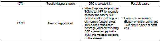
When the power supply to the TCM is cut OFF, for example because the battery is removed, and the self-diagnosis memory function stops, malfunction is detected.
NOTE
:
Since ŌĆ£P1701ŌĆØ will be indicated when replacing TCM, perform diagnosis after
erasing ŌĆ£SELF-DIAG
RESULTSŌĆØ
DTC Logic
DTC DETECTION LOGIC
DTC CONFIRMATION PROCEDURE
NOTE
:
If ŌĆ£DTC CONFIRMATION PROCEDUREŌĆØ has been previously conducted, always turn
ignition switch
OFF and wait at least 10 seconds before conducting the next test.
After the repair, perform the following procedure to confirm the malfunction is eliminated.
1.CHECK DTC DETECTION
 With CONSULT-III
1. Turn ignition switch ON.
2. Wait for at least 2 consecutive seconds.
3. Select ŌĆ£Self Diagnostic ResultsŌĆØ in ŌĆ£TRANSMISSIONŌĆØ.
Is ŌĆ£P1701ŌĆØ detected? YES >> Go to TM-239, "Diagnosis Procedure".
NO >> Check intermittent incident. Refer to GI-42, "Intermittent Incident".
Diagnosis Procedure
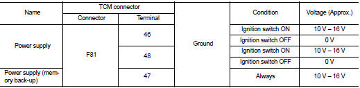
1.CHECK TCM POWER SOURCE
Check voltage between TCM connector terminals and ground.
Is the inspection result normal? YES >> GO TO 4.
NO >> GO TO 2.
2.DETECT MALFUNCTIONING ITEM
Check the following.
ŌĆó Harness for short or open between battery and TCM connector terminal 47
ŌĆó Harness for short or open between ignition switch and TCM connector terminal
46, 48
ŌĆó 10A fuse (No. 55, located in the IPDM E/R)
ŌĆó 10A fuse (No. 33, located in the J/B)
ŌĆó Ignition switch. Refer to PG-15, "Wiring Diagram - IGNITION POWER SUPPLY -".
Is the inspection result normal? YES >> GO TO 3.
NO >> Repair or replace damaged parts.
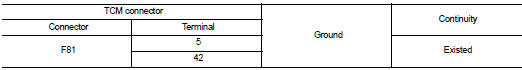
3.CHECK TCM GROUND CIRCUIT
1. Turn ignition switch OFF.
2. Disconnect TCM connector.
3. Check continuity between TCM connector terminals and ground.
Is the inspection result normal? YES >> GO TO 4.
NO >> Repair or replace damaged parts.
4.CHECK TCM
Check TCM input/output signals. Refer to TM-164, "Reference Value".
Is the inspection result normal? YES >> Check intermittent incident. Refer to GI-42, "Intermittent Incident".
NO >> Replace the TCM. Refer to TM-280, "Removal and Installation".
 P1585 G sensor
Description
ŌĆó G sensor is installed to floor under instrument lower cover.
ŌĆó G sensor detects longitudinal G and inclination that affects the vehicle and
outputs to ECM using analog voltage.
...
 P1705 TP sensor
Description
Electric throttle control actuator consists of throttle control motor,
accelerator pedal position sensor, throttle
position sensor etc. The actuator sends a signal to the ECM, and ECM ...
Other materials:
Inspection
OIL LEAKAGE
Check rear final drive surrounding area (oil seal, drain plug, filler plug,
and carrier case, etc.) for oil leakage.
OIL LEVEL
1. Remove filler plug (1) and check oil level from filler plug mounting
hole as shown in the figure.
CAUTION:
Never start engine while checking oil l ...
Draining
WARNING:
ŌĆó Never remove radiator cap when engine is hot. Serious burns may occur from
high-pressure engine
coolant escaping from radiator.
ŌĆó Wrap a thick cloth around the radiator cap. Slowly turn it a quarter of a turn
to release built-up pressure.
Then turn it all the way.
1. Connec ...
Service Notice or Precautions for Transfer
ŌĆó After overhaul refill the transfer with new transfer oil.
ŌĆó Check the oil level or replace the oil only with the vehicle parked on level
surface.
ŌĆó During removal or installation, keep inside of transfer clear of dust or
dirt.
ŌĆó Replace all tires at the same time. Always use tires o ...
