Nissan Juke Service and Repair Manual : P1722 vehicle speed
Description
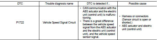
The vehicle speed signal is transmitted from ABS actuator and electric unit (control unit) to TCM by CAN communication line.
DTC Logic
DTC DETECTION LOGIC
DTC CONFIRMATION PROCEDURE
CAUTION:
Always drive vehicle at a safe speed.
NOTE:
If “DTC CONFIRMATION PROCEDURE” has been previously performed, always turn ignition switch OFF and wait at least 10 seconds before performing the next test.
After the repair, perform the following procedure to confirm the malfunction is eliminated.
1.CHECK DTC DETECTION
 With CONSULT-III
1. Turn ignition switch ON.
2. Select “DATA MONITOR” in “TRANSMISSION”.
3. Start engine and maintain the following conditions for at least 5 consecutive seconds.
ACC PEDAL OPEN : 1.0/8 or less VEHICLE SPEED : 30 km/h (19 MPH) or more
Is “P1722” detected? YES >> Go to GI-42, "Intermittent Incident".
NO >> Check intermittent incident. Refer to GI-42, "Intermittent Incident".
Diagnosis Procedure
1.CHECK ABS ACTUATOR AND ELECTRIC UNIT (CONTROL UNIT)
Perform “SELF-DIAG RESULTS”.
Is the inspection result normal? YES >> GO TO 2.
NO >> Repair or replace damaged parts.
2.CHECK INPUT SIGNALS
 With CONSULT-III
1. Start engine.
2. Select “DATA MONITOR”.
3. Drive vehicle and read out the value of “VEHICLE SPEED” and “ESTM VSP SIG”.
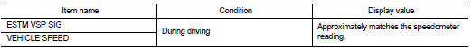
4. Check if there is a great difference between the two values.
Is the inspection result normal? YES >> Check intermittent incident. Refer to GI-42, "Intermittent Incident".
NO >> GO TO 3.
3.CHECK TCM
Check TCM input/output signals. Refer to TM-164, "Reference Value".
Is the inspection result normal? YES >> Check intermittent incident. Refer to GI-42, "Intermittent Incident".
NO >> Replace TCM. Refer to TM-280, "Removal and Installation".
 P1705 TP sensor
Description
Electric throttle control actuator consists of throttle control motor,
accelerator pedal position sensor, throttle
position sensor etc. The actuator sends a signal to the ECM, and ECM ...
 P1723 speed sensor
Description
The secondary speed sensor detects the revolution of parking gear and
generates a pulse signal. The pulse
signal is sent to the TCM, which converts it into vehicle speed.
The prymar ...
Other materials:
P0110 IAT sensor
DTC Logic
DTC DETECTION LOGIC
Diagnosis Procedure
1.CHECK GROUND CONNECTIONS
1. Turn ignition switch OFF.
2. Check ground connection E38. Refer to Ground inspection in GI-44, "Circuit
Inspection".
Is the inspection result normal?
YES >> GO TO 2.
NO >> Repair or ...
Back door opener actuator
Diagnosis Procedure
1.CHECK BACK DOOR OPENER ACTUATOR INPUT SIGNAL
1. Turn ignition switch OFF.
2. Disconnect back door opener assembly connector.
3. Check voltage between back door opener assembly harness connector and ground.
Is the inspection result normal?
YES >> GO TO 3.
NO > ...
Remote keyless entry system (if so equipped)
It is possible to lock/unlock all doors (including the lift gate), and activate
the panic alarm by using the keyfob from outside the vehicle.
Before locking the doors, make sure the key is not left in the vehicle.
The keyfob can operate at a distance of approximately 33 ft (10 m) from the vehic ...
