Nissan Juke Service and Repair Manual : P1723 speed sensor
Description
The secondary speed sensor detects the revolution of parking gear and generates a pulse signal. The pulse signal is sent to the TCM, which converts it into vehicle speed.
The prymary speed sensor detects the primary pulley revolution speed and sends a signal to the TCM.
DTC Logic
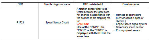
DTC DETECTION LOGIC
DTC CONFIRMATION PROCEDURE
CAUTION:
Always drive vehicle at a safe speed.
NOTE:
If “DTC CONFIRMATION PROCEDURE” has been previously performed, always turn ignition switch OFF and wait at least 10 seconds before performing the next test.
After the repair, perform the following procedure to confirm the malfunction is eliminated.
1.CHECK DTC DETECTION
 With CONSULT-III
1. Turn ignition switch ON.
2. Select “DATA MONITOR” in “TRANSMISSION”.
3. Start engine and maintain the following conditions for at least 5 consecutive seconds
VEHICLE SPEED : 10 km/h (6 MPH) or more
ACC PEDAL OPEN : More than 1.0/8
RANGE : “D” position
ENG SPEED : 450 rpm or more
Driving location : Driving the vehicle uphill (increased
engine load) will help
maintain the driving conditions
required for this test.
Is “P1723” detected? YES >> Go to TM-244, "Diagnosis Procedure".
NO >> Check intermittent incident. Refer to GI-42, "Intermittent Incident".
Diagnosis Procedure
1.CHECK STEP MOTOR FUNCTION
Perform the self-diagnosis check
Is a malfunction in the step motor function indicated in the results? YES >> Repair or replace damaged parts. (Check the step motor function. Refer to TM-252, "DTC Logic".) NO >> GO TO 2.
2.CHECK SECONDARY SPEED SENSOR SYSTEM
Check secondary speed sensor system. Refer to TM-209, "DTC Logic".
Is the inspection result normal? YES >> GO TO 3.
NO >> Repair or replace damaged parts.
3.CHECK PRIMARY SPEED SENSOR SYSTEM
Check primary speed sensor system. Refer to TM-207, "DTC Logic".
Is the inspection result normal? YES >> GO TO 4.
NO >> Repair or replace damaged parts.
4.CHECK ENGINE SPEED SIGNAL SYSTEM
Check engine speed signal system. Refer to TM-212, "DTC Logic".
Is the inspection result normal? YES >> GO TO 5.
NO >> Repair or replace damaged parts.
5.CHECK TCM
Check TCM input/output signals. Refer to TM-164, "Reference Value".
Is the inspection result normal? YES >> Check intermittent incident. Refer to GI-42, "Intermittent Incident".
NO >> Replace TCM.
 P1722 vehicle speed
Description
The vehicle speed signal is transmitted from ABS actuator and electric unit
(control unit) to TCM by CAN communication
line.
DTC Logic
DTC DETECTION LOGIC
DTC CONFIRMATION PROCEDU ...
 P1726 throttle control signal
Description
Electric throttle control actuator consists of throttle control motor,
accelerator pedal position sensor, throttle
position sensor etc. The actuator sends a signal to the ECM, and ECM ...
Other materials:
P1616 ECM
DTC Logic
DTC DETECTION LOGIC
DTC CONFIRMATION PROCEDURE
1.PERFORM DTC CONFIRMATION PROCEDURE FOR MALFUNCTION
1. Turn ignition switch ON amd wait 2 seconds or more.
2. Check DTC in “Self Diagnostic Result” mode of “ENGINE” using CONSULT-III.
Is DTC detected?
YES >> Go to SEC ...
P0420 three way catalyst function
DTC Logic
DTC DETECTION LOGIC
The ECM monitors the switching frequency ratio of air fuel ratio (A/F)
sensor 1 and heated oxygen sensor 2.
A three way catalyst (manifold) with high oxygen storage capacity
will indicate a low switching frequency of heated oxygen sensor 2.
As oxygen storage c ...
If the Li-ion battery becomes completely discharged
Should the power limitation indicator light
illuminate while you are driving your Nissan Leaf, be aware that the system has restricted the output of the traction motor. This is an intentional safety feature designed to preserve remaining energy, and you will notice a correspondin ...
