Nissan Juke Service and Repair Manual : P0868 transmission fluid pressure
Description
The secondary pressure solenoid valve regulates the secondary pressure to suit the driving condition in response to a signal sent from the TCM.
DTC Logic
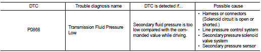
DTC DETECTION LOGIC
DTC CONFIRMATION PROCEDURE
CAUTION:
Always drive vehicle at a safe speed.
NOTE:
If “DTC CONFIRMATION PROCEDURE” has been previously performed, always turn ignition switch OFF and wait at least 10 seconds before performing the next test.
After the repair, perform the following procedure to confirm the malfunction is eliminated.
1.CHECK DTC DETECTION
 With CONSULT-III
1. Turn ignition switch ON.
2. Select “DATA MONITOR” in “TRANSMISSION”.
3. Make sure that output voltage of CVT fluid temperature sensor is within the range below.
ATF TEMP SEN : 1.0 – 2.0 V If out of range, drive the vehicle to decrease the voltage (warm up the fluid) or stop engine to increase the voltage (cool down the fluid)
4. Start engine and maintain the following conditions for at least 10 consecutive seconds.
VEHICLE SPEED (accelerate slowly) : 0 → 50 km/h (31 MPH) ACC PEDAL OPEN : 0.5/8 ‚Äì 1.0/8 RANGE : ‚ÄúD‚Äù position
Is “P0868” detected? YES >> Go to TM-234, "Diagnosis Procedure".
NO >> Check intermittent incident. Refer to GI-42, "Intermittent Incident".
Diagnosis Procedure
1.CHECK LINE PRESSURE
Perform line pressure test. Refer to TM-188, "Inspection and Judgment".
Is the inspection result normal? YES >> GO TO 2.
NO >> Repair or replace damaged parts. Refer to TM-188, "Inspection and Judgment".
2.CHECK SECONDARY PRESSURE SOLENOID VALVE
Check secondary pressure solenoid valve. Refer to TM-225, "DTC Logic".
Is the inspection result normal?
YES >> GO TO 3.
NO >> Repair or replace damaged parts.
3.CHECK LINE PRESSURE SOLENOID VALVE
Check line pressure solenoid valve. Refer to TM-219, "DTC Logic".
Is the inspection result normal? YES >> GO TO 4.
NO >> Repair or replace damaged parts.
4.CHECK SECONDARY PRESSURE SENSOR SYSTEM
Check secondary pressure sensor system. Refer to TM-230, "DTC Logic".
Is the inspection result normal? YES >> GO TO 5.
NO >> Repair or replace damaged parts.
5.CHECK TCM
Check input/output signal. Refer to TM-164, "Reference Value" Is the inspection result normal? YES >> Check intermittent incident. Refer to GI-42, "Intermittent Incident".
NO >> Replace the TCM. Refer to TM-280, "Removal and Installation".
 P0841 transmission fluid pressure SEN/SW A
Description
Using the engine load (throttle position), the primary pulley revolution
speed, and the secondary pulley revolution
speed as input signal, TCM changes the operating pressure of the pri ...
 P1585 G sensor
Description
• G sensor is installed to floor under instrument lower cover.
• G sensor detects longitudinal G and inclination that affects the vehicle and
outputs to ECM using analog voltage.
...
Other materials:
Wiring diagram
AUDIO WITHOUT NAVIGATION
Wiring Diagram
For connector terminal arrangements, harness layouts, and alphabets in a
(option abbreviation; if not
described in wiring diagram), refer to GI-12, "Connector Information/Explanation
of Option Abbreviation".
...
Vacuum lines
MR16DDT : Removal and Installation
REMOVAL
1. Remove the vacuum hose and vacuum piping.
2. Perform inspection after removal. Refer to BR-115, "MR16DDT : Inspection".
INSTALLATION
Note the following, install the vacuum hose.
• When installing vacuum hose, insert it until its tip ...
Exterior rear
1. Lift gate
— Intelligent Key system
2. Rear window wiper and washer
— Switch operation
— Window washer fluid
3. Rear spoiler
4. High-mounted stop light
5. Antenna
— Satellite radio antenna
6. Rear window defroster
7. Fuel-filler door
— Operation
— Fuel recommend ...
