Nissan Juke Service and Repair Manual : P17B4 low brake solenoid
DTC Logic
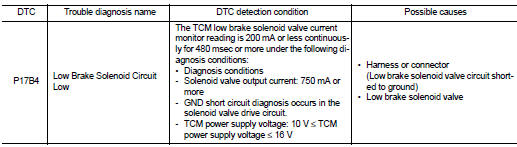
DTC DETECTION LOGIC
DTC CONFIRMATION PROCEDURE
1.PREPARATION BEFORE WORK
If another "DTC CONFIRMATION PROCEDURE" occurs just before, turn ignition switch OFF and wait for at least 10 seconds, then perform the next test.
>> GO TO 2.
2.CHECK DTC DETECTION
1. Start the engine.
2. Shift the selector lever to ŌĆ£DŌĆØ position and wait for 5 seconds or more.
3. Check the first trip DTC.
Is ŌĆ£P17B4ŌĆØ detected? YES >> Go to TM-449, "Diagnosis Procedure".
NO >> INSPECTION END
Diagnosis Procedure
1.CHECK CIRCUIT BETWEEN TCM AND THE CVT UNIT
1. Turn the ignition switch OFF.
2. Disconnect the TCM connector and the CVT unit connector.
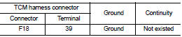
3. Check the continuity between TCM harness connector terminal and ground.
Is the inspection result normal? YES >> GO TO 2.
NO >> Repair or replace the malfunctioning parts.
2.CHECK LOW BRAKE SOLENOID VALVE
Check the low brake solenoid valve. Refer to TM-450, "Component Inspection (Low Brake Solenoid Valve)".
Is the inspection result normal? YES >> Check intermittent incident. Refer to GI-42, "Intermittent Incident".
NO >> Repair or replace the malfunctioning parts.
Component Inspection (Low Brake Solenoid Valve)
1.CHECK LOW BRAKE SOLENOID VALVE
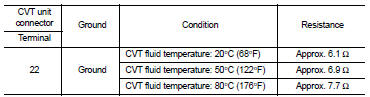
Check the resistance between the CVT unit connector terminal and ground.
Is the inspection result normal? YES >> INSPECTION END
NO >> There is a malfunction of the low brake solenoid valve. Replace the transaxle assembly. Refer to TM-508, "Removal and Installation".
 P173C 2GR incorrect ratio
DTC Logic
DTC DETECTION LOGIC
DTC CONFIRMATION PROCEDURE
CAUTION:
ŌĆó Be sure to perform ŌĆ£TM-447, "Diagnosis Procedure"ŌĆØ and then perform ŌĆ£DTC
CONFIRMATION PROCEDUREŌĆØ.
ŌĆó N ...
 P17B5 low brake solenoid
DTC Logic
DTC DETECTION LOGIC
DTC CONFIRMATION PROCEDURE
1.PREPARATION BEFORE WORK
If another "DTC CONFIRMATION PROCEDURE" occurs just before, turn ignition
switch OFF and wait for a ...
Other materials:
B210D starter relay
DTC Logic
DTC DETECTION LOGIC
NOTE:
ŌĆó If DTC B210D is displayed with DTC U1000, first perform the trouble diagnosis
for DTC U1000. Refer to
PCS-59, "DTC Logic".
ŌĆó If DTC B210D is displayed with DTC B209F, first perform the trouble diagnosis
for DTC B209F. Refer to
SEC-209, &q ...
Door does not lock/unlock with door request switch
All door request switches
ALL DOOR REQUEST SWITCHES : Description
All doors do not lock/unlock using all door request switches.
ALL DOOR REQUEST SWITCHES : Diagnosis Procedure
1.CHECK REMOTE KEYLESS ENTRY FUNCTION
Check remote keyless entry function.
Does door lock/unlock with Intelligent Ke ...
Vehicle-to-vehicle distance control mode limitations
WARNING
Below are the critical operational limitations for the Intelligent Cruise Control (ICC) system in your Nissan Leaf. Operating the vehicle without strict adherence to these guidelines could result in a loss of control, leading to serious injury or death.
The ICC system is ...
