Nissan Juke Service and Repair Manual : P0335 CKP sensor (POS)
DTC Logic
DTC DETECTION LOGIC
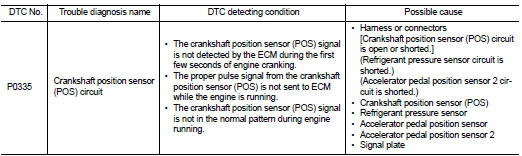
DTC CONFIRMATION PROCEDURE
1.PRECONDITIONING
If DTC Confirmation Procedure has been previously conducted, always turn ignition switch OFF and wait at least 10 seconds before conducting the next test.
TESTING CONDITION:
Before performing the following procedure, confirm that battery voltage is more
than 10.5 V with ignition
switch ON.
>> GO TO 2.
2.PERFORM DTC CONFIRMATION PROCEDURE
1. Start engine and let it idle for at least 5 seconds.
If engine does not start, crank engine for at least 2 seconds.
2. Check 1st trip DTC.
Is 1st trip DTC detected? YES >> Go to EC-656, "Diagnosis Procedure".
NO >> INSPECTION END
Diagnosis Procedure
1.CHECK GROUND CONNECTION
1. Turn ignition switch OFF.
2. Check ground connection E21 and E38. Refer to Ground Inspection in GI-44, "Circuit Inspection".
Is the inspection result normal? YES >> GO TO 2.
NO >> Repair or replace ground connection.
2.CHECK CRANKSHAFT POSITION (CKP) SENSOR (POS) POWER SUPPLY CIRCUIT-I
1. Disconnect crankshaft position (CKP) sensor (POS) harness connector.
2. Turn ignition switch ON.
3. Check the voltage between CKP sensor (POS) harness connector and ground.
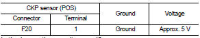
Is the inspection result normal?
YES >> GO TO 8.
NO >> GO TO 3.
3.CHECK CRANKSHAFT POSITION (CKP) SENSOR (POS) POWER SUPPLY CIRCUIT-II
1. Turn ignition switch OFF.
2. Disconnect ECM harness connector.
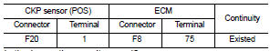
3. Check the continuity between CKP sensor (POS) harness connector and ECM harness connector.
Is the inspection result normal? YES >> GO TO 4.
NO >> Repair open circuit.
4.CHECK SENSOR POWER SUPPLY CIRCUIT
Check harness for short to power and short to ground, between the following terminals.
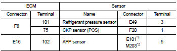
*1: LHD models or RHD models with CVT *2: RHD models with M/T
Is the inspection result normal? YES >> GO TO 5.
NO >> Repair short to ground or short to power in harness or connectors.
5.CHECK REFRIGERANT PRESSURE SENSOR
Check the refrigerant pressure sensor. Refer to EC-790, "Component Function Check".
Is the inspection result normal? YES >> GO TO 6.
NO >> Replace refrigerant pressure sensor.
6.CHECK APP SENSOR
Refer to EC-749, "Component Inspection".
Is the inspection result normal? YES >> GO TO 12.
NO >> GO TO 7.
7.REPLACE ACCELERATOR PEDAL ASSEMBLY
Replace accelerator pedal assembly. Refer to ACC-3, "Exploded View".
>> INSPECTION END
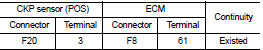
8.CHECK CKP SENSOR (POS) GROUND CIRCUIT FOR OPEN AND SHORT
1. Turn ignition switch OFF.
2. Check the continuity between CKP sensor (POS) harness connector and ECM harness connector.
3. Also check harness for short to ground and short to power.
Is the inspection result normal? YES >> GO TO 9.
NO >> Repair open circuit or short to ground or short to power in harness or connectors.
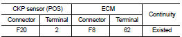
9.CHECK CKP SENSOR (POS) INPUT SIGNAL CIRCUIT FOR OPEN AND SHORT
1. Disconnect ECM harness connector.
2. Check the continuity between CKP sensor (POS) harness connector and ECM harness connector.
3. Also check harness for short to ground and short to power.
Is the inspection result normal? YES >> GO TO 10.
NO >> Repair open circuit or short to ground or short to power in harness or connectors.
10.CHECK CRANKSHAFT POSITION SENSOR (POS)
Refer to EC-658, "Component Inspection".
Is the inspection result normal? YES >> GO TO 11.
NO >> Replace crankshaft position sensor (POS).
11.CHECK GEAR TOOTH
Visually check for chipping signal plate gear tooth.
Is the inspection result normal? YES >> GO TO 12.
NO >> Replace the signal plate.
12.CHECK INTERMITTENT INCIDENT
Refer to GI-42, "Intermittent Incident".
>> INSPECTION END
Component Inspection
1.CHECK CRANKSHAFT POSITION SENSOR (POS)-I
1. Turn ignition switch OFF.
2. Loosen the fixing bolt of the sensor.
3. Disconnect crankshaft position sensor (POS) harness connector.
4. Remove the sensor
5. Visually check the sensor for chipping.
Is the inspection result normal? YES >> GO TO 2.
NO >> Replace crankshaft position sensor (POS).
2.CHECK CRANKSHAFT POSITION SENSOR (POS)-II
Check resistance between crankshaft position sensor (POS) terminals as follows.
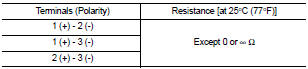
Is the inspection result normal? YES >> INSPECTION END
NO >> Replace crankshaft position sensor (POS).
 P0327, P0328 KS
DTC Logic
DTC DETECTION LOGIC
DTC CONFIRMATION PROCEDURE
1.PRECONDITIONING
If DTC Confirmation Procedure has been previously conducted, always turn
ignition switch OFF and wait at
least 10 se ...
 P0340 CMP sensor (phase)
DTC Logic
DTC DETECTION LOGIC
NOTE:
If DTC P0340 is displayed with DTC P0643, first perform the trouble diagnosis
for DTC P0643. Refer to
EC-686, "DTC Logic".
DTC CONFIRMATION PROCE ...
Other materials:
P0507 ISC system
Description
The ECM controls the engine idle speed to a specified level through the fine
adjustment of the air, which is let
into the intake manifold, by operating the electric throttle control actuator.
The operating of the throttle valve is
varied to allow for optimum control of the engine ...
U1405 engine torque signal
DTC Logic
DTC DETECTION LOGIC
Diagnosis Procedure
1.PERFORM ECM SELF-DIAGNOSIS
Using CONSULT-III, check the “self diagnosis result” of “ENGINE” and repair
or replace any malfunctioning
parts.
>> • Refer to EC-108, "DTC Index". (MR16DDT)
• Refer to EC-522, &qu ...
P0014 EVT control
DTC Logic
DTC DETECTION LOGIC
NOTE:
If DTC P0014 is displayed with DTC P0078, first perform trouble diagnosis for
DTC P0078. Refer to EC-
585, "DTC Logic".
DTC CONFIRMATION PROCEDURE
1.PRECONDITIONING
If DTC Confirmation Procedure has been previously conducted, always perform
...
