Nissan Juke Service and Repair Manual : P0507 ISC system
Description
The ECM controls the engine idle speed to a specified level through the fine adjustment of the air, which is let into the intake manifold, by operating the electric throttle control actuator. The operating of the throttle valve is varied to allow for optimum control of the engine idling speed. The crankshaft position sensor (POS) detects the actual engine speed and sends a signal to the ECM.
The ECM controls the electric throttle control actuator so that the engine speed coincides with the target value memorized in the ECM. The target engine speed is the lowest speed at which the engine can operate steadily.
The optimum value stored in the ECM is determined by taking into consideration various engine conditions, such as during warming up, deceleration, and engine load (air conditioner, power steering and cooling fan operation, etc.).
DTC Logic
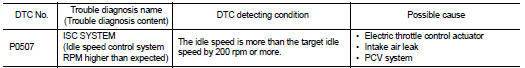
DTC DETECTION LOGIC
NOTE
:
If DTC P0507 is displayed with other DTC, first perform the trouble diagnosis
for the other DTC.
DTC CONFIRMATION PROCEDURE
1.PRECONDITIONING
If DTC Confirmation Procedure has been previously conducted, always perform the following procedure before conducting the next test.
1. Turn ignition switch OFF and wait at least 10 seconds.
2. Turn ignition switch ON.
3. Turn ignition switch OFF and wait at least 10 seconds.
If the target idle speed is out of the specified value, perform EC-136, "Work Procedure", before conducting DTC Confirmation Procedure.
TESTING CONDITION:
• Before performing the following procedure, confirm that battery voltage is
more than 11 V at idle.
• Always perform the test at a temperature above −10°C (14°F).
>> GO TO 2.
2.PERFORM DTC CONFIRMATION PROCEDURE
1. Start engine and warm it up to normal operating temperature.
2. Turn ignition switch OFF and wait at least 10 seconds.
3. Start engine and run it for at least 1 minute at idle speed.
4. Check 1st trip DTC.
Is 1st trip DTC detected? YES >> Proceed to EC-291, "Diagnosis Procedure".
NO >> INSPECTION END
Diagnosis Procedure
1.CHECK PCV HOSE CONNECTION
Confirm that PCV hose is connected correctly.
Is the inspection result normal? YES >> GO TO 2.
NO >> Repair or replace error-detected parts.
2.CHECK INTAKE AIR LEAK
1. Start engine and let it idle.
2. Listen for an intake air leak after the mass air flow sensor.
Is intake air leak detected? YES >> Discover air leak location and repair.
NO >> Replace ECM. Refer to EC-447, "Removal and Installation".
 P0506 ISC system
Description
The ECM controls the engine idle speed to a specified level through the fine
adjustment of the air, which is let
into the intake manifold, by operating the electric throttle control ac ...
 P0520 EOP sensor
DTC Logic
DTC CONFIRMATION PROCEDURE
1.PRECONDITIONING
If DTC Confirmation Procedure has been previously conducted, always perform
the following procedure
before conducting the next test.
1. ...
Other materials:
System temporarily unavailable
Condition A
The AEB with Pedestrian Detection system in your Nissan Leaf may automatically deactivate, accompanied by a blinking warning light, when it encounters environmental factors that temporarily impair its ability to monitor the road. This occurs in the following si ...
Difference between predicted and
actual distances
The superimposed guidelines displayed on the monitor panel and their indicated contact points on the ground are calibrated exclusively for approximate driver reference. Physical obstacles located on steep uphill gradients, downhill slopes, or objects projecting horizontally into mid-air will actuall ...
How to charge/discharge using the quick charge port
The advanced V2X (Vehicle-to-Everything) technology allows your Nissan Leaf to act as a powerful mobile energy resource, enabling the vehicle to supply electricity to a variety of external systems, including residential homes, commercial buildings, and other infrastructure.
The "V2X" ecosystem ...
