
Nissan Leaf 2018-2025 (ZE1) Owner's Manual : Difference between predicted and actual distances
The superimposed guidelines displayed on the monitor panel and their indicated contact points on the ground are calibrated exclusively for approximate driver reference. Physical obstacles located on steep uphill gradients, downhill slopes, or objects projecting horizontally into mid-air will actually be positioned at real-world distances that differ significantly from the relative positions projected on the monitor screen (please refer closely to the operational illustrations below). Whenever you are in doubt about the spatial layout while driving your Nissan Leaf, physically turn your head to check your surroundings as you reverse, or safely bring the vehicle to a complete stop, engage park, and exit the cabin to personally verify the true position of objects behind the bumper.
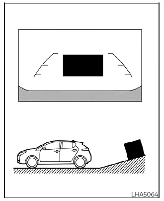
Backing up on a steep uphill
When reversing your vehicle up a steep incline or driveway hill, the flat horizontal distance guidelines and the parallel vehicle width guidelines are projected on the digital screen much closer to the bumper than the actual true physical distance. Always take careful note that any object or low obstacle situated on an uphill grade is physically further away from the rear fascia than it appears on the infotainment monitor.
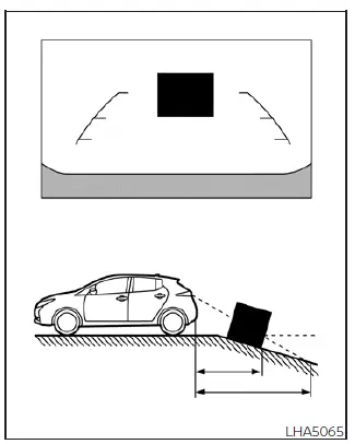
Backing up on a steep downhill
When reversing your vehicle down a steep downhill grade or slope decline, the digital distance guidelines and the parallel vehicle width tracks are projected on the screen much farther away from the rear bumper than the actual true physical distance. Always remember that any obstacle situated on a downhill slope is physically closer to your vehicle panels than it appears on the camera monitor screen.
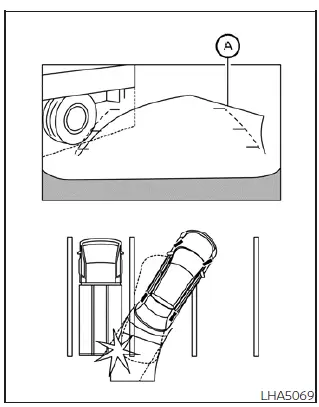
Backing up near a projecting object
The dynamic predicted course lines A may appear to completely clear and not make visual contact with a high projecting object within the digital screen display layout. However, the upper tailgate structure of your Nissan Leaf can still collide with the object if that obstacle projects horizontally into mid-air over the actual physical path of the reversing vehicle.
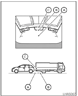
Backing up behind a projecting object
The upper overhanging position C is visually displayed as being farther away than the lower ground-level position B within the camera display interface. However, in real physical space, the projecting point C is actually located at the exact same close distance as the ground-level point A. Your vehicle may strike the overhanging structure when reversing back toward position A if the upper part of the object projects outward over the actual path traveled by your Nissan Leaf.
How to park with predicted course lines
WARNING
- If the factory wheels are swapped out or replaced with different sized tires or alternative aftermarket rim specifications, the built-in trajectory sensor parameters will be altered, which may cause the predicted course lines to be calculated and displayed incorrectly on the console screen.
- When operating on a snow-covered, icy, mud-slicked, or highly slippery road surface, tire traction is reduced, meaning there may be a noticeable difference between the path shown by the predicted course line and the actual physical path traveled by the car.
- If the auxiliary 12V battery is disconnected for servicing or becomes completely discharged, the backup camera tracking memory will temporarily lose its calibration data, and the predicted course lines may be displayed incorrectly on your screen.
If this calibration loss occurs after a power disruption, please perform the following physical driving reset procedures to recalibrate the software system:
- With the vehicle stationary and the primary EV (electric vehicle) system running in READY-to-drive status, turn the steering wheel smoothly all the way from lock to lock in both directions.
- Drive the vehicle forward on a straight road with clearly visible lane markings for a continuous duration of more than 5 minutes.
- When the steering wheel column is rotated or turned while the main power switch is resting in the auxiliary ACC position rather than the fully operational ON position, the tracking sensor synchronization will lag, and the predicted course lines may be displayed incorrectly.
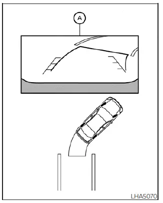
1. Always conduct a thorough visual check of the entire surrounding area to ensure that the designated parking space and entry boundaries are completely safe before initiating any vehicle backing maneuvers.
2. A live, wide-angle rear view of the vehicle perimeter is automatically generated and displayed on the main dashboard display screen A the exact moment the electronic shift selector is moved into the R (Reverse) position.
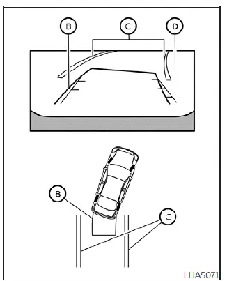
3. Slowly back up the vehicle into the lane, gently adjusting your steering wheel inputs so that the curved graphic paths of the predicted course lines B enter safely into the open borders of the target parking space C.
4. Carefully maneuver the steering wheel to guide the straight vehicle width guide lines D until they are completely parallel to the painted side lines of the parking space C, using the dynamic trajectory of the predicted course lines as a constant tracking guide.
5. When your vehicle has been guided into the parking space completely and rests straight, move the electronic shift selector to the P (Park) position and firmly engage the parking brake before powering down the powertrain system.
 Intelligent Around View Monitor
system operation
Intelligent Around View Monitor
system operation
To display the multiple synchronized perspective views, the advanced Intelligent Around View Monitor system utilizes a network of four ultra-wide-angle digital cameras strategica ...
 How to switch the display
With the primary power switch sitting in the active ON position, you can easily activate the system by pressing the physical hardware CAMERA button on the console bezel or by moving the electronic shi ...
Other materials:
B210D starter relay
DTC Logic
DTC DETECTION LOGIC
NOTE:
• If DTC B210D is displayed with DTC U1000, first perform the trouble diagnosis
for DTC U1000. Refer to
PCS-59, "DTC Logic".
• If DTC B210D is displayed with DTC B209F, first perform the trouble diagnosis
for DTC B209F. Refer to
SEC-209, &q ...
Checking engine coolant level
Check the coolant level in the reservoir when the engine is cold. If the coolant
level is below the MIN level 2 , open the reservoir cap and add coolant up to the
MAX level 1 . If the reservoir is empty, check the coolant level in the radiator
when the engine is cold. If there is insufficien ...
B1138, B1139, B1140, B1141, B1142, B1143 diagnosis sensor unit
DTC Logic
DTC DETECTION LOGIC
DTC CONFIRMATION PROCEDURE
1.CHECK SELF-DIAG RESULT
With CONSULT-III
1. Turn ignition switch ON.
2. Perform “Self Diagnostic Result� mode of “AIR BAG� using CONSULT-III.
Without CONSULT-III
1. Turn ignition switch ON.
2. Check the air bag warning la ...
