Nissan Juke Service and Repair Manual : P0520 EOP sensor
DTC Logic
DTC CONFIRMATION PROCEDURE
1.PRECONDITIONING
If DTC Confirmation Procedure has been previously conducted, always perform the following procedure before conducting the next test.
1. Turn ignition switch OFF and wait at least 10 seconds.
2. Turn ignition switch ON.
3. Turn ignition switch OFF and wait at least 10 seconds.
>> GO TO 2.
2.PERFORM DTC CONFIRMATION PROCEDURE
1. Turn ignition switch ON and wait at least 5 seconds.
2. Check 1st trip DTC.
Is 1st trip DTC detected? YES >> Proceed to EC-293, "Diagnosis Procedure".
NO >> INSPECTION END
Diagnosis Procedure
1.CHECK ENGINE OIL
1. Turn ignition switch OFF.
2. Check engine oil level and pressure. Refer to LU-8, "Inspection".
Is inspection result normal? YES >> GO TO 2.
NO >> Repair or replace error-detected parts.
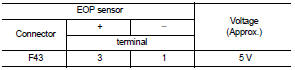
2.CHECK EOP SENSOR POWER SUPPLY-I
1. Disconnect EOP sensor connector.
2. Turn ignition switch ON.
3. Check the voltage between EOP sensor harness connector terminals.
Inspection result normal? YES >> GO TO 7.
NO >> GO TO 3.
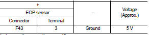
3.CHECK EOP SENSOR POWER SUPPLY-II
Check the voltage between EOP sensor harness connector and the ground.
Is inspection result normal? YES >> GO TO 5.
NO >> GO TO 4.
4.CHECK SENSOR POWER SUPPLY CIRCUIT
1. Turn ignition switch OFF.
2. Disconnect ECM harness connector.
3. Check harness connector for short to power and short to ground, between the following terminals.
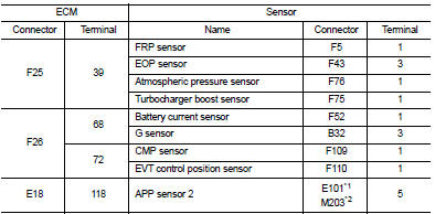
*1: LHD models or RHD with CVT models *2: RHD with M/T models
Is inspection result normal? YES >> Perform the trouble diagnosis for power supply circuit.
NO >> Repair or replace error-detected parts.
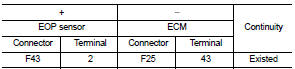
5.CHECK EOP SENSOR GROUND CIRCUIT
1. Turn ignition switch OFF.
2. Disconnect ECM harness connector.
3. Check the continuity between EOP sensor harness connector and ECM harness connector.
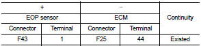
4. Also check harness for short to power.
Is inspection result normal? YES >> GO TO 6.
NO >> Repair or replace error-detected parts.
6.CHECK ECM GROUND CIRCUIT
Check the continuity between ECM harness connector and ground.
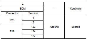
Is inspection result normal? YES >> Check intermittent incident. Refer to GI-42, "Intermittent Incident".
NO >> Repair or replace error-detected parts.
7.CHECK EOP SENSOR SIGNAL CIRCUIT
1. Turn ignition switch OFF.
2. Disconnect ECM harness connector.
3. Check the continuity between EOP sensor harness connector and ECM harness connector.
4. Also check harness for short to ground and to power.
Is inspection result normal? YES >> GO TO 8.
NO >> Repair or replace error-detected parts.
8.CHECK EOP SENSOR
Refer to EC-296, "Component Inspection".
Is inspection result normal? YES >> Check intermittent incident. Refer to GI-42, "Intermittent Incident".
NO >> Repair or replace error-detected parts.
Component Inspection
1.CHECK EOP SENSOR
1. Turn ignition switch OFF.
2. Disconnect EOP sensor harness connector.
3. Check resistance between EOP sensor connector terminals.
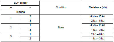
Is the inspection result normal? YES >> INSPECTION END.
NO >> Replace EOP sensor. Refer to EM-103, "Exploded View".
 P0507 ISC system
Description
The ECM controls the engine idle speed to a specified level through the fine
adjustment of the air, which is let
into the intake manifold, by operating the electric throttle control ac ...
 P0524 engine oil pressure
DTC Logic
DTC DETECTION LOGIC
NOTE:
If DTC P0524 is displayed with DTC P0520, P0075, or P0081, perform trouble
diagnosis for DTC P0520,
P0075, or P0081 first. Refer to EC-176, "DTC Logic&qu ...
Other materials:
Component parts
Component Parts Location
1. Door request switch (driver side)
2. Door mirror (driver side)
3. Remote keyless entry receiver
Refer to DLK-21,
"Component Parts Location"
4. Door mirror remote control switch
5. BCM
Refer to BCS-6, "BODY CONTROL
SYSTEM : Component Parts Loca ...
On board diagnostic (OBD) system
Diagnosis Description
The ECM controls the display on the instrument panel of certain information
relating to the operation of the
engine.
Four functions are involved here: The OBD malfunction indicator [MI (Yellow)]
for the EOBD (European On
Board Diagnostics), the pre/post heating, the e ...
P0420 three way catalyst function
DTC Logic
DTC DETECTION LOGIC
The ECM monitors the switching frequency ratio of air fuel ratio (A/F)
sensor 1 and heated oxygen sensor 2.
A three way catalyst (manifold) with high oxygen storage capacity
will indicate a low switching frequency of heated oxygen sensor 2.
As oxygen storage c ...
