Nissan Juke Service and Repair Manual : U0122 Vehicle dynamics control module
Description
CAN (Controller Area Network) is a serial communication line for real time application. It is an on-vehicle multiplex communication line with high data communication speed and excellent error detection ability. Many electronic control units are equipped onto a vehicle, and each control unit shares information and links with other control units during operation (not independent). In CAN communication, control units are connected with 2 communication lines (CAN H line, CAN L line) allowing a high rate of information transmission with less wiring.
Each control unit transmits/receives data but selectively reads required data only.
DTC Logic
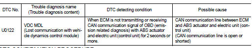
DTC DETECTION LOGIC
DTC CONFIRMATION PROCEDURE
1.PERFORM DTC CONFIRMATION PROCEDURE
1. Turn ignition switch ON and wait at least 3 seconds.
2. Check DTC.
Is DTC detected? YES >> Proceed to EC-160, "Diagnosis Procedure".
NO >> INSPECTION END
Diagnosis Procedure
Perform the trouble diagnosis for CAN communication system. Refer to LAN-17, "Trouble Diagnosis Flow Chart".
 U0101 Can comm circuit
Description
CAN (Controller Area Network) is a serial communication line for real time
application. It is an on-vehicle multiplex
communication line with high data communication speed and excelle ...
 U1001 Can comm circuit
Description
CAN (Controller Area Network) is a serial communication line for real time
application. It is an on-vehicle multiplex
communication line with high data communication speed and excelle ...
Other materials:
Diagnosis system (IPDM E/R)
Consult-III Function (IPDM E/R)
APPLICATION ITEM
CONSULT-III performs the following functions via CAN communication with IPDM
E/R.
SELF DIAGNOSTIC RESULT
Refer to PCS-25, "DTC Index".
DATA MONITOR
Monitor item
ACTIVE TEST
Test item
...
Super lock does not operate
All door
ALL DOOR : Diagnosis Procedure
1.CHECK SUPER LOCK ACTUATOR
Check front driver side super lock actuator.
Refer to DLK-99, "DRIVER SIDE : Component Function Check".
Is the inspection result normal?
YES >> GO TO 2.
NO >> Repair or replace the malfunctioning p ...
Jump starting
To start your engine with a booster battery, the instructions and precautions
below must be followed.
WARNING
• If done incorrectly, jump starting can lead to a battery explosion, resulting
in severe injury or death.
It could also damage your vehicle.
• Explosive hydrogen gas is always p ...
