Nissan Juke Service and Repair Manual : U0101 Can comm circuit
Description
CAN (Controller Area Network) is a serial communication line for real time application. It is an on-vehicle multiplex communication line with high data communication speed and excellent error detection ability. Many electronic control units are equipped onto a vehicle, and each control unit shares information and links with other control units during operation (not independent). In CAN communication, control units are connected with 2 communication lines (CAN H line, CAN L line) allowing a high rate of information transmission with less wiring.
Each control unit transmits/receives data but selectively reads required data only.
DTC Logic
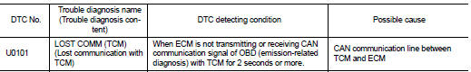
DTC DETECTION LOGIC
DTC CONFIRMATION PROCEDURE
1.PERFORM DTC CONFIRMATION PROCEDURE
1. Turn ignition switch ON and wait at least 3 seconds.
2. Check DTC.
Is DTC detected? YES >> Proceed to EC-159, "Diagnosis Procedure".
NO >> INSPECTION END
Diagnosis Procedure
Perform the trouble diagnosis for CAN communication system. Refer to LAN-17, "Trouble Diagnosis Flow Chart".
 Power supply and ground circuit
Diagnosis Procedure
1.CHECK FUSE
Is the fuse fusing?
YES >> Replace the fuse after repairing the applicable circuit.
NO >> GO TO 2.
2.CHECK GROUND CONNECTION
1. Turn ignition swi ...
 U0122 Vehicle dynamics control
module
U0122 Vehicle dynamics control
module
Description
CAN (Controller Area Network) is a serial communication line for real time
application. It is an on-vehicle multiplex
communication line with high data communication speed and excelle ...
Other materials:
C1115 wheel sensor
DTC Logic
DTC CONFIRMATION PROCEDURE
1.PRECONDITIONING
If “DTC CONFIRMATION PROCEDURE” has been previously conducted, always turn
ignition switch OFF and
wait at least 10 seconds before conducting the next test.
>> GO TO 2.
2.CHECK DTC DETECTION
With CONSULT-III.
1. Stat th ...
B2556 Push-button ignition switch
DTC Logic
DTC DETECTION LOGIC
DTC CONFIRMATION PROCEDURE
1.PERFORM DTC CONFIRMATION PROCEDURE
1. Press push-button ignition switch under the following condition.
- Brake pedal: Not depressed
2. Release push-button ignition switch and wait 100 seconds or more.
3. Check DTC in “Self Diagnos ...
Power window motor
DRIVER SIDE
DRIVER SIDE : Component Function Check
1. CHECK FRONT POWER WINDOW MOTOR (DRIVER SIDE) OPERATION
Check front power window motor (driver side) operation with power window main
switch.
Is the inspection result normal?
YES >> INSPECTION END
NO >> Refer to PWC-26, " ...
