Nissan Juke Service and Repair Manual : Power supply and ground circuit
Diagnosis Procedure
1.CHECK FUSE
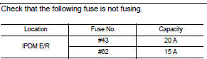
Is the fuse fusing? YES >> Replace the fuse after repairing the applicable circuit.
NO >> GO TO 2.
2.CHECK GROUND CONNECTION
1. Turn ignition switch OFF.
2. Check ground connection E21 and E38. Refer to GI-44, "Circuit Inspection".
Is the inspection result normal? YES >> GO TO 3.
NO >> Repair or replace ground connection.
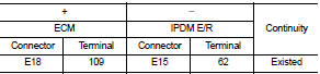
3.CHECK ECM GROUND CIRCUIT
1. Disconnect ECM harness connectors.
2. Check the continuity between ECM harness connector and ground.
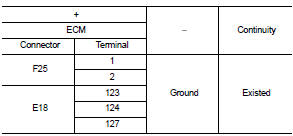
Is the inspection result normal? YES >> GO TO 4.
NO >> Repair or replace error-detected parts.
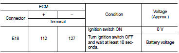
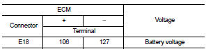
4.CHECK ECM POWER SUPPLY (MAIN)-I
1. Reconnect ECM harness connector.
2. Turn ignition switch ON.
3. Check the voltage between ECM harness connector terminals.
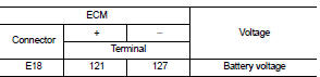
Is the inspection result normal? YES >> GO TO 5.
NO >> GO TO 6.
5.CHECK ECM POWER SUPPLY (MAIN)-II
1. Turn ignition switch OFF and wait at least 10 seconds.
2. Check the voltage between ECM harness connector terminals as per the following.
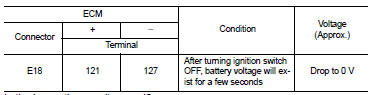
Is the inspection result normal? YES >> GO TO 9.
NO >> GO TO 7.
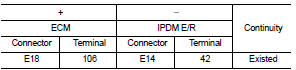
6.CHECK ECM POWER SUPPLY (MAIN) CIRCUIT
1. Turn ignition switch OFF.
2. Disconnect ECM harness connectors.
3. Disconnect IPDM E/R harness connector.
4. Check the continuity between ECM harness connector and IPDM E/R harness connector.
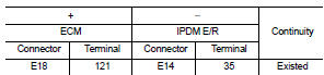
5. Also check harness for short to ground.
Is the inspection result normal? YES >> Perform the trouble diagnosis for power supply circuit.
NO >> Repair or replace error-detected parts.
7.CHECK ECM RELAY CONTROL SIGNAL
Check the voltage between ECM harness connector terminals as per the following.
Is the inspection result normal? YES >> Check Intermittent Incident. Refer to GI-42, "Intermittent Incident".
NO >> GO TO 8.
8.CHECK ECM RELAY CONTROL SIGNAL CIRCUIT
1. Turn ignition switch OFF.
2. Disconnect ECM harness connector.
3. Disconnect IPDM E/R harness connector.
4. Check the continuity between ECM harness connector and IPDM E/R harness connector.
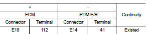
5. Also check harness for short to ground and to power.
Is the inspection result normal? YES >> Replace IPDM E/R. Refer to PCS-34, "Removal and Installation".
NO >> Repair or replace error-detected parts.
9.CHECK IGNITION SWITCH SIGNAL
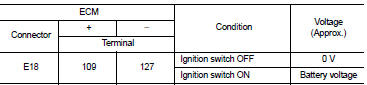
Is the inspection result normal? YES >> GO TO 11.
NO >> GO TO 10.
10.CHECK IGNITION SWITCH SIGNAL CIRCUIT
1. Turn ignition switch OFF.
2. Disconnect ECM harness connector.
3. Disconnect IPDM E/R harness connector.
4. Check the continuity between ECM harness connector and IPDM E/R harness connector.
5. Also check harness for short to ground and to power.
Is the inspection result normal? YES >> Perform the trouble diagnosis for power supply circuit.
NO >> Repair or replace error-detected parts.
11.CHECK ECM POWER SUPPLY (BACK-UP)
Check the voltage between ECM harness connector terminals.
Is the inspection result normal? YES >> Check Intermittent Incident. Refer to GI-42, "Intermittent Incident".
NO >> GO TO 12.
12.CHECK ECM POWER SUPPLY (BACK-UP) CIRCUIT
1. Turn ignition switch OFF.
2. Disconnect ECM harness connector.
3. Disconnect IPDM E/R harness connector.
4. Check the continuity between ECM harness connector and IPDM E/R harness connector.
5. Also check harness for short to ground.
Is the inspection result normal? YES >> Perform the trouble diagnosis for power supply circuit.
NO >> Repair or replace error-detected parts.
 Trouble diagnosis - specification
value
Trouble diagnosis - specification
value
Description
The specification (SP) value indicates the tolerance of the value that is
displayed in “SPEC” of “DATA MONITOR”
mode of CONSULT-III during normal operation of the Engine Contr ...
 U0101 Can comm circuit
Description
CAN (Controller Area Network) is a serial communication line for real time
application. It is an on-vehicle multiplex
communication line with high data communication speed and excelle ...
Other materials:
U1010 control unit (CAN)
Description
Initial diagnosis of A/C auto amp.
DTC Logic
DTC DETECTION LOGIC
DTC CONFIRMATION PROCEDURE
1.PERFORM DTC CONFIRMATION PROCEDURE
With CONSULT-III
1. Turn ignition switch ON.
2. Select “Self Diagnostic Result” mode of “HVAC” using CONSULT-III.
3. Check DTC.
Is DTC de ...
Door motor
Diagnosis Procedure
NOTE:
If all of door motor DTCs are detected, check this circuit.
1.CHECK DOOR MOTOR POWER SUPPLY
1. Turn ignition switch ON.
2. Check voltage between intake door motor harness connector and ground.
Is the inspection result normal?
YES >> GO TO 2.
NO >> ...
Assembly and Installation
• Use torque wrench to tighten bolts or nuts to specification.
• When tightening nuts and bolts, as a basic rule, equally tighten in several
different steps starting with the
ones in center, then ones on inside and outside diagonally in this order. If the
order of tightening is specified,
...
