Nissan Juke Service and Repair Manual : Electrical load signal
Description
The electrical load signal (Headlamp switch signal, rear window defogger switch signal, etc.) is transferred via the CAN communication line.
Component Function Check
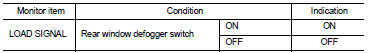
1.CHECK REAR WINDOW DEFOGGER SWITCH FUNCTION
 With CONSULT-III
1. Turn ignition switch ON.
2. Select ŌĆ£DATA MONITORŌĆØ mode of ŌĆ£ENGINEŌĆØ using CONSULT-III.
3. Select ŌĆ£LOAD SIGNALŌĆØ and check indication as per the following conditions.
Is the inspection result normal? YES >> GO TO 2.
NO >> Proceed to EC-418, "Diagnosis Procedure".
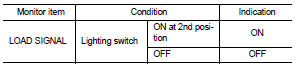
2.CHECK LIGHTING SWITCH FUNCTION
 With CONSULT-III
Check ŌĆ£LOAD SIGNALŌĆØ indication as per the following conditions.
Is the inspection result normal? YES >> GO TO 3.
NO >> Proceed to EC-418, "Diagnosis Procedure".
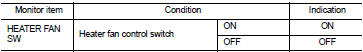
3.CHECK HEATER FAN CONTROL SWITCH FUNCTION
 With CONSULT-III
Select ŌĆ£HEATER FAN SWŌĆØ and check indication as per the following conditions.
Is the inspection result normal? YES >> INSPECTION END
NO >> Proceed to EC-418, "Diagnosis Procedure".
Diagnosis Procedure
1.INSPECTION START
Confirm the malfunctioning circuit (rear window defogger, headlamp or heater fan). Refer to EC-418, "Component Function Check".
Which circuit is related to the incident? Rear window defogger>>GO TO 2.
Headlamp>>GO TO 3.
Heater fan>>GO TO 4.
2.CHECK REAR WINDOW DEFOGGER SYSTEM
Check the rear window defogger system. Refer to DEF-25, "Work Flow".
>> INSPECTION END 3.CHECK HEADLAMP SYSTEM
Check the headlamp system. Refer to EXL-43, "Work Flow".
>> INSPECTION END 4.CHECK HEATER FAN CONTROL SYSTEM
Check the heater fan control system. refer to HA-72, "Work Flow".
>> INSPECTION END
 Ignition signal
Component Function Check
1.INSPECTION START
Turn ignition switch OFF, and restart engine.
Does the engine start?
YES >> GO TO 2.
NO >> Proceed to EC-414, "Diagnosis Procedure ...
 Cooling fan
Component Function Check
1.CHECK COOLING FAN FUNCTION
With CONSULT-III
1. Turn ignition switch ON.
2. Perform ŌĆ£FAN DUTY CONTROLŌĆØ in ŌĆ£ACTIVE TESTŌĆØ mode of ŌĆ£ENGINEŌĆØ using
CONSULT-III.
...
Other materials:
Wiring diagram
NISSAN DYNAMIC CONTROL SYSTEM
Wiring Diagram
For connector terminal arrangements, harness layouts, and alphabets in a
(option abbreviation; if not
described in wiring diagram), refer to GI-12, "Connector Information/Explanation
of Option Abbreviation".
...
TCM
Exploded View
1. Bracket
2. TCM
:Vehicle front
: N┬Ęm (kg-m, in-lb)
Removal and Installation
CAUTION:
When replacing TCM, note the ŌĆ£CVTF DETERIORATION DATEŌĆØ value displayed on
CONSULT-III ŌĆ£CONFORM
CVTF DETERIORTNŌĆØ in MAINTENANCE BOOKLET, before start the operation.
NOTE:
When ...
Power supply and ground circuit
Navi control unit
NAVI CONTROL UNIT : Diagnosis Procedure
1.CHECK FUSE
Check for blown fuses.
Is inspection result OK?
YES >> GO TO 2.
NO >> Be sure to eliminate cause of malfunction before installing new fuse.
2.CHECK POWER SUPPLY CIRCUIT
Check voltage between NAVI control ...
