Nissan Juke Service and Repair Manual : B2198 nats antenna AMP.
DTC Logic
DTC DETECTION LOGIC
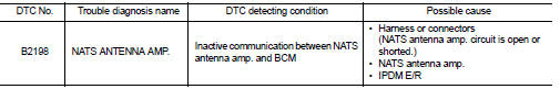
DTC CONFIRMATION PROCEDURE
1.PERFORM DTC CONFIRMATION PROCEDURE 1
1. Contact Intelligent Key backside to push-button ignition switch.
2. Check DTC in “Self Diagnostic Result” mode of “BCM” using CONSULT-III.
Is DTC detected? YES >> Go to SEC-65, "Diagnosis Procedure".
NO >> GO TO 2.
2.PERFORM DTC CONFIRMATION PROCEDURE 2
1. Press the push-button ignition switch.
2. Check DTC in “Self Diagnostic Result” mode of “BCM” using CONSULT-III.
Is DTC detected? YES >> Go to SEC-65, "Diagnosis Procedure".
NO >> INSPECTION END
Diagnosis Procedure
1.CHECK FUSE
1. Turn ignition switch OFF.
2. Check that the following fuse in IPDM E/R is not blown.

Is the fuse fusing? YES >> Replace the blown fuse after repairing the cause of blowing.
NO >> GO TO 2.
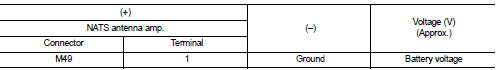
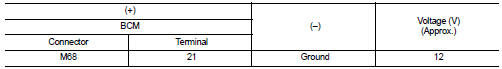
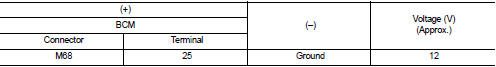
2.CHECK NATS ANTENNA AMP. POWER SUPPLY
1. Disconnect NATS antenna amp. connector.
2. Check voltage between NATS antenna amp. harness connector and ground.
Is the inspection result normal? YES >> GO TO 4.
NO >> GO TO 3.
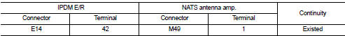
3.CHECK NATS ANTENNA AMP. POWER SUPPLY CIRCUIT
1. Disconnect IPDM E/R connector.
2. Check continuity between IPDM E/R harness connector and NATS antenna amp. connector.
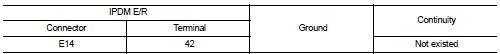
3. Check continuity between IPDM E/R harness connector and ground.
Is the inspection result normal? YES >> Replace IPDM E/R. Refer to PCS-34, "Removal and Installation".
NO >> Repair or replace harness.
4.CHECK NATS ANTENNA AMP. OUTPUT SIGNAL 1
1. Connect NATS antenna amp. connector.
2. Disconnect BCM connector.
3. Check voltage between BCM harness connector and ground.
Is the inspection result normal? YES >> GO TO 6.
NO >> GO TO 5.
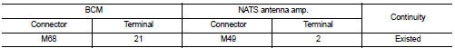
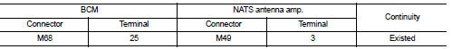
5.CHECK NATS ANTENNA AMP. OUTPUT SIGNAL CIRCUIT 1
1. Disconnect NATS antenna amp. connector.
2. Check continuity between BCM harness connector and NATS antenna amp. connector.
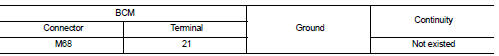
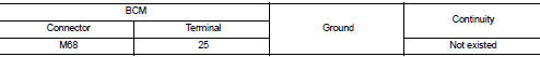
3. Check continuity between BCM harness connector and ground.
Is the inspection result normal? YES >> Replace NATS antenna amp. Refer to SEC-167, "Removal and Installation".
NO >> Repair or replace harness.
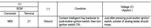
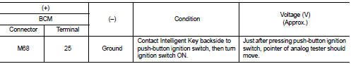
6.CHECK NATS ANTENNA AMP. COMMUNICATION SIGNAL 1
1. Connect BCM connector.
2. Check voltage between BCM harness connector and ground using analog tester.
Is the inspection result normal?
YES >> GO TO 7.
NO >> Replace NATS antenna amp. Refer to SEC-167, "Removal and Installation".
7.CHECK NATS ANTENNA AMP. OUTPUT SIGNAL 2
1. Disconnect BCM connector.
2. Check voltage between BCM harness connector and ground.
Is the inspection result normal? YES >> GO TO 9.
NO >> GO TO 8.
8.CHECK NATS ANTENNA AMP. OUTPUT SIGNAL CIRCUIT 2
1. Disconnect NATS antenna amp. connector.
2. Check continuity between BCM harness connector and NATS antenna amp. connector.
3. Check continuity between BCM harness connector and ground.
Is the inspection result normal? YES >> Replace NATS antenna amp. Refer to SEC-167, "Removal and Installation".
NO >> Repair or replace harness.
9.CHECK NATS ANTENNA AMP. COMMUNICATION SIGNAL 2
1. Connect BCM connector.
2. Check voltage between BCM harness connector and ground using analog tester
Is the inspection result normal? YES >> GO TO 10.
NO >> Replace NATS antenna amp. Refer to SEC-167, "Removal and Installation".
10.CHECK NATS ANTENNA AMP. GROUND CIRCUIT
1. Disconnect NATS antenna amp. connector.
2. Check continuity between NATS antenna amp. harness connector and ground.
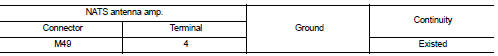
Is the inspection result normal?
YES >> GO TO 11.
NO >> Repair or replace harness.
11.CHECK INTERMITTENT INCIDENT
Refer to GI-42, "Intermittent Incident".
>> INSPECTION END
 B2196 dongle unit
Description
BCM performs ID verification between BCM and dongle unit.
When verification result is OK, BCM permits cranking.
DTC Logic
DTC DETECTION LOGIC
DTC CONFIRMATION PROCEDURE
1.PERFORM ...
 B2013 steering lock unit
DTC Logic
DTC DETECTION LOGIC
DTC CONFIRMATION PROCEDURE
1.PERFORM DTC CONFIRMATION PROCEDURE
1. Lock the steering.
NOTE:
3. Press the push-button ignition switch.
4. Check DTC in “Self ...
Other materials:
Automatic air conditioner (with Integrated Control System)
1. AUTO button/Temperature control dial
2. OFF button
3. A/C button
4. CLIMATE button
5. Display screen
6. Air flow control buttons
7. Fan speed control dial
8. Front defroster button
9. Air intake button (Outside air circulation
/Air recirculation
)
10. Rear window defroster button ( ...
Precaution for Supplemental Restraint System (SRS) "AIR BAG" and "SEAT BELT
PRE-TENSIONER"
The Supplemental Restraint System such as “AIR BAG” and “SEAT BELT PRE-TENSIONER”,
used along
with a front seat belt, helps to reduce the risk or severity of injury to the
driver and front passenger for certain
types of collision. Information necessary to service the system safely is
...
Stall test
Work Procedure
INSPECTION
1. Check the engine oil level. Replenish if necessary. Refer to LU-25,
"Inspection".
2. Check for leak of the CVT fluid. Refer to TM-480, "Inspection".
3. Drive for about 10 minutes to warm up the vehicle so that the CVT fluid
temperature is 50 t ...
