Nissan Juke Service and Repair Manual : B2196 dongle unit
Description
BCM performs ID verification between BCM and dongle unit.
When verification result is OK, BCM permits cranking.
DTC Logic
DTC DETECTION LOGIC
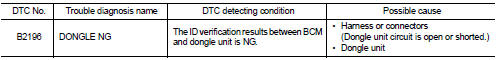
DTC CONFIRMATION PROCEDURE
1.PERFORM DTC CONFIRMATION PROCEDURE
1. Turn ignition switch ON.
2. Turn ignition switch OFF.
3. Turn ignition switch ON.
4. Check DTC in ÔÇťSelf-diagnosis resultÔÇŁ mode of ÔÇťBCMÔÇŁ using CONSULT-III.
Is the DTC detected? YES >> Refer to SEC-63, "Diagnosis Procedure".
NO >> INSPECTION END
Diagnosis Procedure
1.PERFORM INITIALIZATION
1. Perform initialization of BCM and reregistration of all Intelligent Keys using CONSULT-III.
For initialization and registration procedures, refer to CONSULT-III Operation Manual NATS-IVIS/NVIS.
2. Start the engine.
Dose the engine start? YES >> INSPECTION END
NO >> GO TO 2.
2.CHECK DONGLE UNIT CIRCUIT
1. Turn ignition switch OFF.
2. Disconnect BCM connector and dongle unit connector.
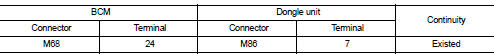
3. Check continuity between BCM harness connector and dongle unit harness connector.
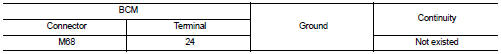
4. Check continuity between BCM harness connector and ground.
Is the inspection result normal? YES >> GO TO 3.
NO >> Repair or replace harness.
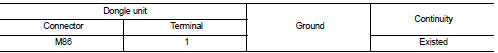
3.CHECK DONGLE UNIT GROUND CIRCUIT
Check continuity between dongle unit harness connector and ground.
Is the inspection result normal? YES >> Replace dongle unit.
NO >> Repair or replace harness.
 B2195 anti-scanning
DTC Logic
DTC DETECTION LOGIC
DTC CONFIRMATION PROCEDURE
1.PERFORM DTC CONFIRMATION PROCEDURE
1. Turn ignition switch ON.
2. Check DTC in ÔÇťSelf Diagnostic ResultÔÇŁ mode of ÔÇťBCMÔÇŁ using CO ...
 B2198 nats antenna AMP.
DTC Logic
DTC DETECTION LOGIC
DTC CONFIRMATION PROCEDURE
1.PERFORM DTC CONFIRMATION PROCEDURE 1
1. Contact Intelligent Key backside to push-button ignition switch.
2. Check DTC in ÔÇťSelf Diagn ...
Other materials:
Turbocharger
Exploded View
1. Exhaust manifold
2. Turbocharger
3. Gasket
4. Turbocharger outlet duct
5. Oil outlet hose
6. Clamp
7. Oil return pipe
8. Gasket
9. Washer
10. Oil supply tube
11. O-ring
A. To EGR tube
B. To air inlet pipe
C. To turbocharge air inlet pipe
D. To diesel partic ...
Gas station information
FUEL RECOMMENDATION:
NISSAN recommends the use of unleaded premium gasoline with an octane rating
of at least 91 AKI (Anti-Knock Index) number (Research octane number 96).
If unleaded premium gasoline is not available, you may use unleaded regular gasoline
with an octane rating of at least 87 ...
B1215, B1216, B1217 satellite sensor LH
DTC Logic
DTC DETECTION LOGIC
DTC CONFIRMATION PROCEDURE
1.CHECK SELF-DIAG RESULT
With CONSULT-III
1. Turn ignition switch ON.
2. Perform ÔÇťSelf Diagnostic ResultÔÇŁ mode of ÔÇťAIR BAGÔÇŁ using CONSULT-III.
Without CONSULT-III
1. Turn ignition switch ON.
2. Check the air bag warning la ...
