Nissan Juke Service and Repair Manual : B210C starter control relay
DTC Logic
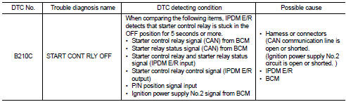
DTC DETECTION LOGIC
NOTE
:
ŌĆó If DTC B210C is displayed with DTC U1000, first perform the trouble diagnosis
for DTC U1000. Refer to
PCS-30, "DTC Logic".
ŌĆó When IPDM E/R power supply voltage is low (Approx. 7 - 8 V for about 1 second), the DTC B210C may be detected.
DTC CONFIRMATION PROCEDURE
1.PERFORM DTC CONFIRMATION PROCEDURE
1. Press push-button ignition switch under the following conditions to start engine, and wait 5 seconds or more.
- Selector lever: In the P position - Brake pedal: Depressed 2. Check DTC in ŌĆ£Self Diagnostic ResultŌĆØ mode of ŌĆ£IPDM E/RŌĆØ using CONSULT-III.
Is DTC detected? YES >> Go to SEC-144, "Diagnosis Procedure".
NO >> GO TO 2.
2.PERFORM DTC CONFIRMATION PROCEDURE 2
1. Stop engine.
2. Perform DTC CONFIRMATION PROCEDURE for DTC P1650. Refer to EC-366, "DTC Logic" (MR16DDT) or EC-725, "DTC Logic" (HR16DE).
3. Turn ignition switch ON.
4. Check DTC in ŌĆ£Self Diagnostic ResultŌĆØ mode of ŌĆ£IPDM E/RŌĆØ using CONSULT-III.
Is DTC detected? YES >> Refer to SEC-144, "Diagnosis Procedure".
NO >> INSPECTION END
Diagnosis Procedure
1.INSPECTION START
Perform inspection in accordance with procedure that confirms DTC.
Which procedure confirms DTC? DTC confirmation procedure 1>>GO TO 2.
DTC confirmation procedure 2>>GO TO 4.
2.CHECK DTC OF BCM
Check DTC in ŌĆ£Self Diagnostic ResultŌĆØ mode of ŌĆ£BCMŌĆØ using CONSULT-III.
Is DTC detected? YES >> Perform the trouble diagnosis related to the detected DTC. Refer to BCS-67, "DTC Index".
NO >> GO TO 3.
3.INSPECTION START
1. Turn ignition switch ON.
2. Select ŌĆ£Self Diagnostic ResultŌĆØ mode of ŌĆ£IPDM E/RŌĆØ using CONSULT-III.
3. Touch ŌĆ£ERASEŌĆØ.
4. Perform DTC CONFIRMATION PROCEDURE for DTC B210C. Refer to SEC-144, "DTC Logic".
Is DTC detected? YES >> GO TO 6.
NO >> INSPECTION END
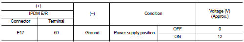
4.CHECK IGNITION POWER SUPLLY NO.2 SIGNAL
1. Turn ignition switch OFF.
2. Disconnect IPDM E/R connector.
3. Check voltage between IPDM E/R harness connector and ground.
Is the inspection result normal? YES >> Replace IPDM E/R. Refer to PCS-34, "Removal and Installation".
NO >> GO TO 5.
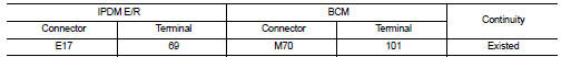
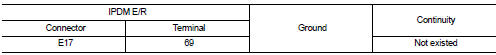
5.CHECK BCM INPUT SIGNAL CIRCUIT
1. Disconnect BCM connector.
2. Check continuity between IPDM E/R harness connector and BCM harness connector.
3. Check continuity between transmission range switch harness connector and ground.
Is the inspection result normal? YES >> GO TO 6.
NO >> Repair or replace harness.
6.REPLACE BCM
1. Replace BCM. Refer to BCS-93, "Removal and Installation".
2. Perform DTC CONFIRMATION PROCEDURE for DTC B210C. Refer to SEC-144, "DTC Logic".
Is the inspection result normal? YES >> INSPECTION END
NO >> Replace IPDM E/R. Refer to PCS-34, "Removal and Installation".
 B210B starter control relay
DTC Logic
DTC DETECTION LOGIC
NOTE:
If DTC B210B is displayed with DTC U1000, first perform the trouble diagnosis
for DTC U1000. Refer to PCS-
30, "DTC Logic".
DTC CONFIRMATION PROC ...
 B210D starter relay
DTC Logic
DTC DETECTION LOGIC
NOTE:
If DTC B210D is displayed with DTC U1000, first perform the trouble diagnosis
for DTC U1000. Refer to PCS-
30, "DTC Logic".
DTC CONFIRMATION PROC ...
Other materials:
Positive crankcase ventilation
Inspection
1.CHECK PCV VALVE
With engine running at idle, remove PCV valve from rocker cover. A
properly working valve makes a hissing noise as air passes through
it. A strong vacuum should be felt immediately when a finger is
placed over valve inlet.
Is the inspection result normal?
YES &g ...
Writing unit parameter
Description
Perform writing unit parameter of electric controlled coupling after
replacing 4WD control module, rear final
drive assembly or electric controlled coupling. Refer to DLN-39, "Work
Procedure".
Work Procedure
1.WRITE UNIT PARAMETER
With CONSULT-III
1. Confirm the unit ...
P2263 TC system
DTC Logic
DTC DETECTION LOGIC
Diagnosis Procedure
1.CHECK VACUUM HOSES AND VACUUM GALLERY
1. Turn ignition switch OFF.
2. Check vacuum hoses and vacuum gallery for clogging, cracks
or improper connection. Refer to EC-825, "TURBOCHARGER
BOOST CONTROL : Vacuum Hose Drawing".
Is t ...
