Nissan Juke Service and Repair Manual : B210D starter relay
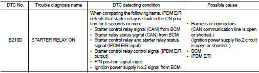
DTC Logic
DTC DETECTION LOGIC
NOTE
:
If DTC B210D is displayed with DTC U1000, first perform the trouble diagnosis
for DTC U1000. Refer to PCS-
30, "DTC Logic".
DTC CONFIRMATION PROCEDURE
1.PERFORM DTC CONFIRMATION PROCEDURE 1
1. Press push-button ignition switch under the following conditions to start engine, and wait 5 seconds or more.
- Selector lever: In the P position - Brake pedal: Depressed 2. Check DTC in ÔÇťSelf Diagnostic ResultÔÇŁ mode of ÔÇťIPDM E/RÔÇŁ using CONSULT-III.
Is DTC detected? YES >> Go to SEC-146, "Diagnosis Procedure".
NO >> GO TO 2.
2.PERFORM DTC CONFIRMATION PROCEDURE 2
1. Stop engine.
2. Perform DTC CONFIRMATION PROCEDURE for DTC P1650. Refer to EC-366, "DTC Logic" (MR16DDT) or EC-725, "DTC Logic" (HR16DE).
3. Turn ignition switch ON.
4. Check DTC in ÔÇťSelf Diagnostic ResultÔÇŁ mode of ÔÇťIPDM E/RÔÇŁ using CONSULT-III.
Is DTC detected? YES >> Refer to SEC-144, "Diagnosis Procedure".
NO >> INSPECTION END
Diagnosis Procedure
1.INSPECTION START
Perform inspection in accordance with procedure that confirms DTC.
Which procedure confirms DTC? DTC confirmation procedure 1>>GO TO 2.
DTC confirmation procedure 2>>GO TO 3.
2.INSPECTION START
1. Turn ignition switch ON.
2. Select ÔÇťSelf Diagnostic ResultÔÇŁ mode of ÔÇťIPDM E/RÔÇŁ using CONSULT-III.
3. Touch ÔÇťERASEÔÇŁ.
4. Perform DTC CONFIRMATION PROCEDURE for DTC B210D. Refer to SEC-146, "DTC Logic".
Is DTC detected? YES >> Replace IPDM E/R. Refer to PCS-34, "Removal and Installation".
NO >> INSPECTION END
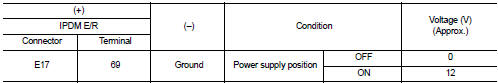
3.CHECK IGNITION POWER SUPLLY NO.2 SIGNAL
1. Turn ignition switch OFF.
2. Disconnect IPDM E/R connector.
3. Check voltage between IPDM E/R harness connector and ground.
Is the inspection result normal? YES >> Replace IPDM E/R. Refer to PCS-34, "Removal and Installation".
NO >> GO TO 4.
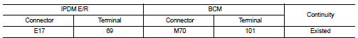
4.CHECK BCM INPUT SIGNAL CIRCUIT
1. Disconnect BCM connector.
2. Check continuity between IPDM E/R harness connector and BCM harness connector.
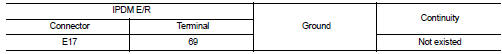
3. Check continuity between transmission range switch harness connector and ground.
Is the inspection result normal? YES >> GO TO 5.
NO >> Repair or replace harness.
5.REPLACE BCM
1. Replace BCM. Refer to BCS-93, "Removal and Installation".
2. Perform DTC CONFIRMATION PROCEDURE for DTC B210D Refer to SEC-146, "DTC Logic".
Is the inspection result normal? YES >> INSPECTION END
NO >> Replace IPDM E/R. Refer to PCS-34, "Removal and Installation".
 B210C starter control relay
DTC Logic
DTC DETECTION LOGIC
NOTE:
ÔÇó If DTC B210C is displayed with DTC U1000, first perform the trouble diagnosis
for DTC U1000. Refer to
PCS-30, "DTC Logic".
ÔÇó When IPDM E/R po ...
 B210E starter relay
DTC Logic
DTC DETECTION LOGIC
NOTE:
ÔÇó If DTC B210E is displayed with DTC U1000, first perform the trouble diagnosis
for DTC U1000. Refer to
PCS-30, "DTC Logic".
ÔÇó If DTC B210E is ...
Other materials:
Door does not lock/unlock with door lock and unlock
switch
All door
ALL DOOR : Description
All doors do not lock/unlock using door lock and unlock switch.
ALL DOOR : Diagnosis Procedure
1.CHECK DOOR LOCK AND UNLOCK SWITCH
Check door lock and unlock switch.
Refer to DLK-79, "DRIVER SIDE : Component Function Check".
Is the inspection resu ...
Parking brake switch
Component Function Check
1.CHECK PARKING BRAKE SWITCH OPERATION
Operate the parking brake lever. Then check that the brake warning lamp in
the combination meter turns ON/
OFF correctly.
Is the inspection result normal?
YES >> INSPECTION END
NO >> Proceed to BRC-208, "Diagn ...
Warning/Indicator lights (yellow)
or
Anti-lock Braking System (ABS) warning light
When you place the power switch in the ON or "READY to drive" position, the Anti-lock Braking System (ABS) warning light will illuminate briefly and then extinguish. This serves as a standard system self-check to confirm ...
