Nissan Juke Service and Repair Manual : Rear washer nozzle and tube
Hydraulic Layout
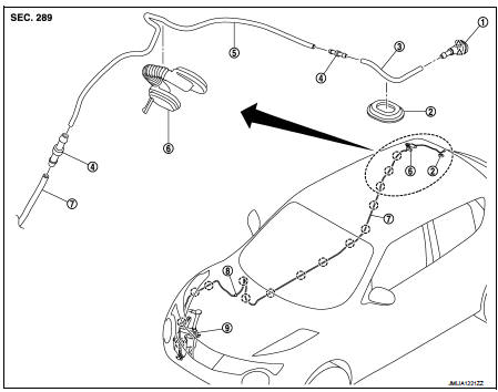
1. Rear washer nozzle
2. Plug
3. Rear washer tube
4. Joint
5. Second washer tube
6. Back door seal rubber
7. Front washer tube
 : Clip
 : Pawl
Removal and Installation
REMOVAL
1. Remove luggage side upper finisher RH. Refer to INT-32, "LUGGAGE SIDE UPPER FINISHER : Removal and Installation".
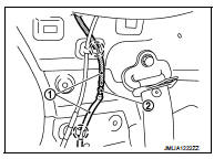
2. Disconnect rear washer tube (2) fixing clip and then remove rear washer tube joint (2) from rear washer tube.
 : Clip
3. Fully open back door.
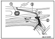
4. Remove back door seal rubber (2), and then remove rear washer tube (3) from back door seal rubber.
5. Remove plug (1).
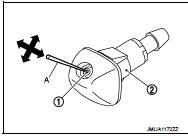
6. Disengage rear washer nozzle (1) fixing pawl with a flat-bladed screwdriver (A) and remove the rear washer nozzle.
CAUTION:
Wrap the flat-bladed screwdriver into a protective tape (B)
to protect the part from damage.
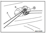
7. Remove rear washer nozzle from the rear washer tube.
INSTALLATION
Install in the reverse order of removal.
Inspection and Adjustment
INSPECTION
Washer Nozzle Inspection Check that air can pass through the hose by blowing forward (toward the nozzle), and check that air cannot pass through by sucking.
ADJUSTMENT
Washer Nozzle Spray Position adjustment Adjust spray positions to match the positions shown in the figure
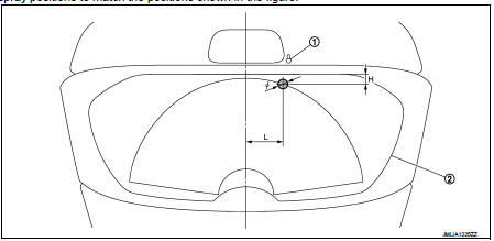
1. Rear washer nozzle 2. Black print frame line

Insert a needle or similar object (A) into the spray opening (1) and move up/down and left/right to adjust the spray position.
NOTE
:
If wax or dust gets into the spray opening of rear washer nozzle (2),
remove wax or dust with a needle or small pin.
 Rear wiper motor
Exploded View
1. Rear wiper motor
2. Rear wiper blade
3. Rear wiper arm
4. Rear wiper arm cover
5. Rear wiper pivot seal
A : Model for cold areas
: Pawl
: N·m (kg-m, in-lb)
: N·m (kg-m ...
 Defogger
...
Other materials:
System setting
Temperature Setting Trimmer
DESCRIPTION
If the temperature felt by the customer is different from the air flow
temperature controlled by the temperature
setting, the A/C auto amp. control temperature can be adjusted to compensate for
the temperature setting.
HOW TO SET
With CONSULT-III
P ...
P0745 pressure control solenoid A
DTC Logic
DTC DETECTION LOGIC
DTC CONFIRMATION PROCEDURE
NOTE:
If “DTC CONFIRMATION PROCEDURE” has been previously performed, always turn
ignition switch
OFF and wait at least 10 seconds before performing the next test.
After the repair, perform the following procedure to confirm the ...
Camshaft valve clearance
Inspection and Adjustment
INSPECTION
Perform inspection as follows after removal, installation or replacement of
camshaft or valve-related parts, or if
there is unusual engine conditions regarding valve clearance.
1. Remove rocker cover. Refer to EM-178, "Removal and Installation".
...
