Nissan Juke Service and Repair Manual : Diagnosis system (TCM)
CONSULT-III Function (TRANSMISSION)
CONSULT-III can display each diagnostic item using the diagnostic test modes shown below.
FUNCTION
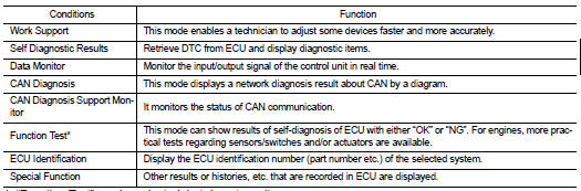
*: “Function Test” can be selected, but do not use it.
WORK SUPPORT MODE
Display Item List
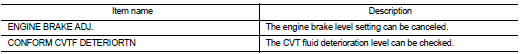
Engine Brake Adjustment
“ENGINE BRAKE LEVEL”
0: Initial set value (Engine brake level control is activated)
OFF: Engine brake level control is deactivated.
CAUTION:
Mode of ‚Äú+1‚Äù‚Äú0‚Äù‚Äú−1‚Äù‚Äú−2‚Äù‚ÄúOFF‚Äù can be selected by pressing the ‚ÄúUP‚Äù‚ÄúDOWN‚Äù on
CONSULT-III screen.
However, do not select mode other than ‚Äú0‚Äù and ‚ÄúOFF‚Äù. If the ‚Äú+1‚Äù or ‚Äú−1‚Äù or ‚Äú‚Äì2‚Äù is selected, that might cause the irregular driveability.
Check CVT Fluid Deterioration Date
“CVTF DETERIORATION DATE” 210000 or more: It is necessary to change CVT fluid.
Less than 210000: It is not necessary to change CVT fluid.
CAUTION:
Touch “CLEAR” after changing CVT fluid, and then erase “CVTF DETERIORATION
DATE”.
SELF-DIAGNOSTIC RESULT MODE
Refer to TM-171, "DTC Index".
DATA MONITOR MODE
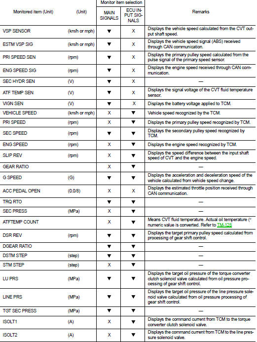
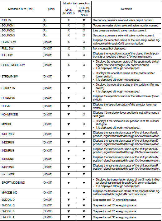
Display Items List
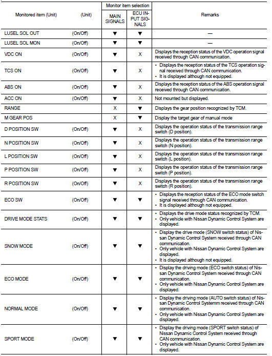
Diagnostic Tool Function
 OBD SELF-DIAGNOSTIC PROCEDURE
(WITH GST)
Refer to EC-72, "Diagnosis Description".
 On board diagnostic (OBD) system
Diagnosis Description
DESCRIPTION
The CVT system has two self-diagnostic systems.
The first is the emission-related on board diagnostic system (OBD) performed by
the TCM in combination with
th ...
 Ecu diagnosis informatioN
TCM
Reference Value
VALUES ON THE DIAGNOSIS TOOL
*1: Means CVT fluid temperature. Convert numerical values for actual fluid
temperature °C (°F). Refer to TM-128, "ATFTEMP COUNT
Co ...
Other materials:
Sill cover
Exploded View
1. Screw grommet
2. Screw grommet
3. Sill cover
4. Wind defle
Removal and Installation
REMOVAL
1. Remove sill cover front end fixing screw (A).
2. Remove sill cover rear end fixing screw (A).
3. Remove sill cover lower side fixing screws.
4. Fully open front door and ...
Adjustment of steering angle sensor neutral position
Description
Always adjust the neutral position of steering angle sensor before driving
when the following operation is performed.
Work Procedure
ADJUST THE NEUTRAL POSITION OF STEERING ANGLE SENSOR
CAUTION:
Always use CONSULT-III when adjusting the neutral position of steering angle
senso ...
P0506 ISC system
Description
The ECM controls the engine idle speed to a specified level through the fine
adjustment of the air, which is let
into the intake manifold, by operating the electric throttle control actuator.
The operating of the throttle valve is
varied to allow for optimum control of the engine ...
