Nissan Juke Service and Repair Manual : Ecu diagnosis informatioN
TCM
Reference Value
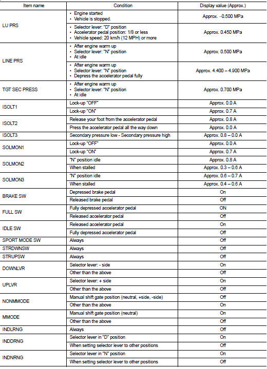
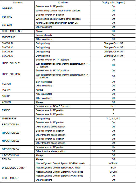
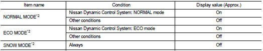
VALUES ON THE DIAGNOSIS TOOL
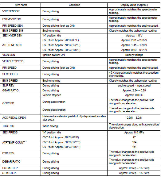
*1: Means CVT fluid temperature. Convert numerical values for actual fluid temperature ┬░C (┬░F). Refer to TM-128, "ATFTEMP COUNT Conversion Table".
TERMINAL LAYOUT

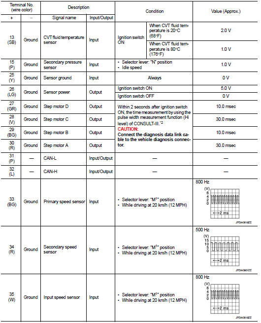
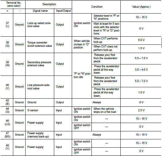
PHYSICAL VALUES
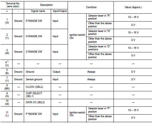
*1: This harness is not used.
*2: A circuit tester cannot be used to test this item.
Fail-safe
The TCM has an electrical fail-safe mode. In this mode TCM is operator even if there is an error in a main electronic control input/output signal circuit.
Description
When a malfunction is detected in each sensor, switch, solenoid or others, this
function provides control to
minimize reduction of drivability so that durability of transmission assembly
can be acquired.
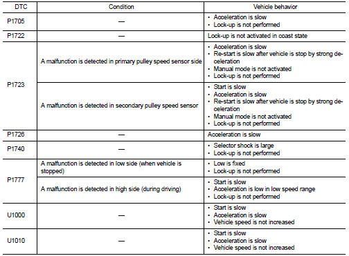
DTC Inspection Priority Chart
If some DTCs are displayed at the same time, perform inspections one by one based on the following priority chart.
NOTE
:
If DTC ÔÇťU1000ÔÇŁ is displayed with other DTCs, first perform the trouble diagnosis
for DTC ÔÇťU1000ÔÇŁ.
Refer to TM-195.

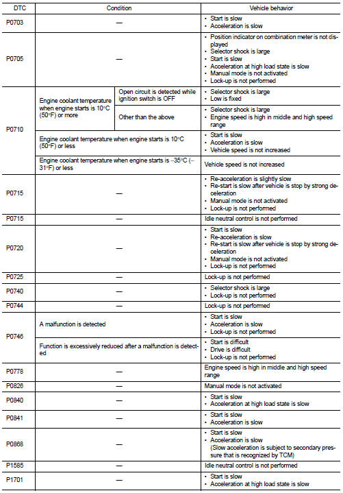
DTC Index
NOTE
:
If DTC ÔÇťU1000ÔÇŁ is displayed with other DTCs, first perform the trouble diagnosis
for DTC ÔÇťU1000ÔÇŁ.
Refer to TM-195.
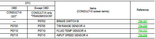
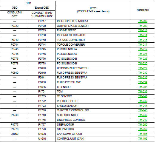
*: These numbers are prescribed by ISO 15031-5.
 Diagnosis system (TCM)
CONSULT-III Function (TRANSMISSION)
CONSULT-III can display each diagnostic item using the diagnostic test modes
shown below.
FUNCTION
*: ÔÇťFunction TestÔÇŁ can be selected, but do not use i ...
 Wiring diagram
...
Other materials:
Connector Information/Explanation of Option Abbreviation
CONNECTOR LIST
Connector information and harness layout are described in ÔÇťPOWER SUPPLY,
GROUND & CIRCUIT ELEMENTSÔÇŁ
Section.
EXPLANATION OF OPTION ABBREVIATION
HOW TO USE CONNECTOR INFORMATION
Description
...
Liquid Gasket
REMOVAL OF LIQUID GASKET
ÔÇó After removing mounting nuts and bolts, separate the mating surface
using the seal cutter [SST: KV10111100] (A) and remove old
liquid gasket sealing.
CAUTION:
Be careful not to damage the mating surfaces.
ÔÇó Tap the seal cutter [SST: KV10111100] to insert it (B) ...
P1616 ECM
DTC Logic
DTC DETECTION LOGIC
DTC CONFIRMATION PROCEDURE
1.PERFORM DTC CONFIRMATION PROCEDURE FOR MALFUNCTION
1. Turn ignition switch ON amd wait 2 seconds or more.
2. Check DTC in ÔÇťSelf Diagnostic ResultÔÇŁ mode of ÔÇťENGINEÔÇŁ using CONSULT-III.
Is DTC detected?
YES >> Go to SEC ...
