Nissan Juke Service and Repair Manual : A/C switch
Component Function Check
1.CHECK A/C ON SIGNAL
 With CONSULT-III
1. Turn ignition switch ON.
2. Select “AIR CONDITIONER” of “BCM” using CONSULT-III.
3. Select “AIR COND SW” in “DATA MONITOR” mode, and check status under the following condition.
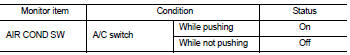
Is the inspection result normal? YES >> INSPECTION END
NO >> Refer to HAC-220, "Diagnosis Procedure".
Diagnosis Procedure
1.CHECK A/C SWITCH POWER SUPPLY
1. Turn ignition switch OFF.
2. Disconnect A/C control connector.
3. Turn ignition switch ON.
4. Check output waveform between A/C control harness connector and ground with using oscilloscope.
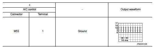
Is the inspection result normal? YES >> GO TO 2.
NO >> GO TO 3.
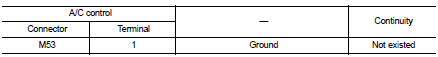
2.CHECK A/C SWITCH GROUND CIRCUIT FOR OPEN
1. Turn ignition switch OFF.
2. Disconnect BCM connector.
3. Check continuity between A/C control harness connector and ground.
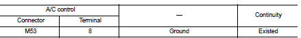
Is the inspection result normal? YES >> Replace A/C control. Refer to HAC-239, "Removal and Installation".
NO >> Repair harness or connector.
3.CHECK A/C SWITCH POWER SUPPLY CIRCUIT FOR OPEN
1. Turn ignition switch OFF.
2. Disconnect BCM connector.
3. Check continuity between A/C control harness connector and BCM harness connector.
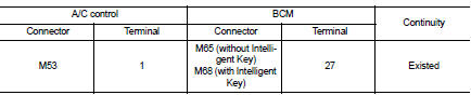
Is the inspection result normal? YES >> GO TO 4.
NO >> Repair harness or connector.
4.CHECK A/C SWITCH POWER SUPPLY CIRCUIT FOR SHORT
Check continuity between A/C control harness connector and ground.
Is the inspection result normal? YES >> Replace BCM. Refer to BCS-93, "Removal and Installation" (with Intelligent Key) or BCS-161, "Removal and Installation" (without Intelligent Key).
NO >> Repair harness or connector.

 Blower fan on signal
Component Function Check
1.CHECK BLOWER FAN ON SIGNAL
With CONSULT-III
1. Turn ignition switch ON.
2. Select “AIR CONDITIONER” of “BCM” using CONSULT-III.
3. Select “FAN ON SIG” in †...
Other materials:
P2A00 A/F sensor 1
DTC Logic
DTC DETECTION LOGIC
To judge the malfunction, the A/F signal computed by ECM from the A/F sensor
1 signal is monitored so it will
not shift to LEAN side or RICH side.
DTC CONFIRMATION PROCEDURE
1.PRECONDITIONING
If DTC Confirmation Procedure has been previously conducted, always ...
Fillet molding
Exploded View
1. Grommet
2. Clip
3. Clip
4. Front fillet molding
5. Rear fillet molding
: Pawl
: Do not reuse
Front fillet molding
FRONT FILLET MOLDING : Removal and Installation
REMOVAL
1. Remove front fillet molding fixing clips.
2. Remove front fillet molding front side fixing pa ...
A/C on signal
Component Function Check
1.CHECK A/C ON SIGNAL
With CONSULT-III
1. Turn ignition switch ON.
2. Operate blower motor.
3. Select “AIR CONDITIONER” of “BCM” using CONSULT-III.
4. Select “AIR COND SW” in “DATA MONITOR” mode.
5. Check A/C ON signal when the A/C switch is operated.
...
