Nissan Juke Service and Repair Manual : Blower fan on signal
Component Function Check
1.CHECK BLOWER FAN ON SIGNAL
 With CONSULT-III
1. Turn ignition switch ON.
2. Select “AIR CONDITIONER” of “BCM” using CONSULT-III.
3. Select “FAN ON SIG” in “DATA MONITOR” mode, and check status under the following condition.
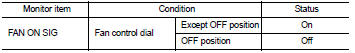
Is the inspection result normal? YES >> INSPECTION END
NO >> Refer to HAC-222, "Diagnosis Procedure".
Diagnosis Procedure
1.CHECK FAN SWITCH POWER SUPPLY SIGNAL
1. Turn ignition switch OFF.
2. Disconnect A/C control harness connector.
3. Turn ignition switch ON.
4. Check output waveform between A/C control and ground with using oscilloscope.
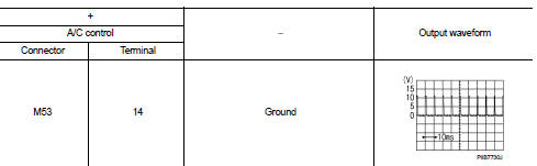
Is the inspection result normal? YES >> Replace A/C control. Refer to HAC-239, "Removal and Installation".
NO >> GO TO 2.
2.CHECK BLOWER FAN ON SIGNAL CIRCUIT FOR OPEN
1. Turn ignition switch OFF.
2. Disconnect BCM connector.
3. Check continuity A/C control harness connector and BCM harness connector.
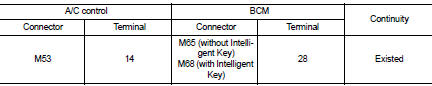
Is the inspection result normal? YES >> GO TO 3.
NO >> Repair harness or connector.
3.CHECK BLOWER FAN ON SIGNAL CIRCUIT FOR SHORT
Check continuity between A/C control harness connector and ground.
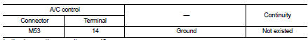
Is the inspection result normal? YES >> Replace BCM. Refer to BCS-93, "Removal and Installation" (with Intelligent Key) or BCS-161, "Removal and Installation" (without Intelligent Key).
NO >> Repair harness or connector.
 A/C switch
Component Function Check
1.CHECK A/C ON SIGNAL
With CONSULT-III
1. Turn ignition switch ON.
2. Select “AIR CONDITIONER” of “BCM” using CONSULT-III.
3. Select “AIR COND SW” in “DATA MONITOR” mode, ...
 Thermo control amplifier
Component Function Check
1.CHECK A/C ON SIGNAL
With CONSULT-III
1. Turn ignition switch ON.
2. Select “AIR CONDITIONER” of “BCM” using CONSULT-III.
3. Select “THERMO AMP” in “DATA MONITOR” mode, ...
Other materials:
Front oil seal
FRONT OIL SEAL : Removal and Installation
REMOVAL
1. Remove the following parts.
• Front fender protector (RH): Refer to EXT-22, "Exploded View".
• Drive belt: Refer to EM-20, "Exploded View".
• Crankshaft pulley: Refer to EM-67, "Exploded View".
2. Remove front ...
Component parts
Component Parts Location
1. Back door lock assembly
2. Front door lock assembly (driver
side)
3. Front door switch (driver side)
4. Power window main switch
(door lock/unlock switch)
5. Key switch
6. Combination meter
7. Door lock status indicator
8. Remote keyless entry receiver
9. ...
Precaution for Supplemental Restraint System (SRS) "AIR BAG" and "SEAT BELT
PRE-TENSIONER"
The Supplemental Restraint System such as “AIR BAG” and “SEAT BELT PRE-TENSIONER”,
used along
with a front seat belt, helps to reduce the risk or severity of injury to the
driver and front passenger for certain
types of collision. Information necessary to service the system safely is
include ...
