Nissan Juke Service and Repair Manual : Thermo control amplifier
Component Function Check
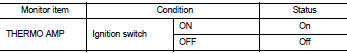
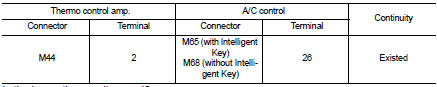
1.CHECK A/C ON SIGNAL
 With CONSULT-III
1. Turn ignition switch ON.
2. Select ŌĆ£AIR CONDITIONERŌĆØ of ŌĆ£BCMŌĆØ using CONSULT-III.
3. Select ŌĆ£THERMO AMPŌĆØ in ŌĆ£DATA MONITORŌĆØ mode, and check status under the following condition.
Is the inspection result normal? YES >> INSPECTION END
NO >> Refer to HAC-224, "Diagnosis Procedure".
Diagnosis Procedure
1.CHECK FUSE
1. Turn ignition switch OFF.
2. Check 10A fuse (No. 15, located in fuse block (J/B)].
NOTE
:
Refer to PG-22, "Fuse, Connector and Terminal Arrangement".
Is the inspection result normal? YES >> GO TO 2.
NO >> Replace the blown fuse after repairing the affected circuit if a fuse is blown.
2.CHECK THERMO CONTROL AMP. POWER SUPPLY
1. Turn ignition switch OFF.
2. Disconnect thermo control amp. connector.
3. Turn ignition switch ON.
4. Check voltage between thermo control amp. harness connector and ground.
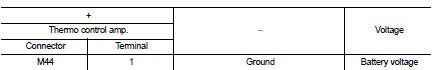
Is the inspection result normal? YES >> GO TO 3.
NO >> Repair harness or connector between thermo control amp. and fuse.
3.CHECK THERMO CONTROL AMP. GROUND CIRCUIT FOR OPEN
1. Turn ignition switch OFF.
2. Check continuity between thermo control amp. harness connector and ground.
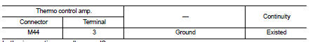
Is the inspection result normal? YES >> GO TO 4.
NO >> Repair harness or connector.
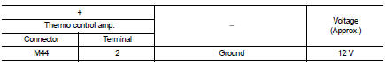
4.CHECK THERMO CONTROL AMP. SIGNAL
1. Turn ignition switch ON.
2. Check voltage between thermo control amp. harness connector and ground.
Is the inspection result normal? YES >> Replace thermo control amp. Refer to HAC-240, "Removal and Installation".
NO >> GO TO 5.
5.CHECK THERMO CONTROL AMP. SIGNAL CIRCUIT FOR OPEN
1. Turn ignition switch OFF.
2. Disconnect BCM connector.
3. Check continuity between thermo control amp. harness connector and BCM harness connector.
Is the inspection result normal? YES >> Replace BCM. Refer to BCS-93, "Removal and Installation" (with Intelligent Key) or BCS-161, "Removal and Installation" (without Intelligent Key).
NO >> Repair harness or connector.
 Blower fan on signal
Component Function Check
1.CHECK BLOWER FAN ON SIGNAL
With CONSULT-III
1. Turn ignition switch ON.
2. Select ŌĆ£AIR CONDITIONERŌĆØ of ŌĆ£BCMŌĆØ using CONSULT-III.
3. Select ŌĆ£FAN ON SIGŌĆØ in ŌĆ ...
 A/C indicator
Diagnosis Procedure
1.CHECK SYMPTOM
Check symptom.
A/C indicator dose not turn ON>>GO TO 2.
A/C indicator dose not turn OFF>>GO TO 6.
2.CHECK FUSE
1. Turn ignition switch OFF.
...
Other materials:
System
Relay control system
RELAY CONTROL SYSTEM : System Diagram
*1: Except for MR16DDT engine models
*2: For MR16DDT engine models
RELAY CONTROL SYSTEM : System Description
IPDM E/R activates the internal control circuit to perform the relay ON-OFF
control according to the input signals
from va ...
Camshaft
Exploded View
1. Camshaft position sensor (PHASE)
2. O-ring
3. Camshaft bracket
4. Camshaft (EXH)
5. Camshaft sprocket (EXH)
6. Camshaft sprocket (INT)
7. Camshaft (INT)
8. Valve lifter (EXH)
9. Valve lifter (INT)
10. Signal plate (INT)
11 Signal plate (EXH)
A.Tightening must be ...
Parking brake
WARNING
Be absolutely sure that the mechanical or electronic parking brake is completely released before driving your vehicle. Failure to do so could cause rapid brake overheating, subsequent friction brake failure, and lead to a serious accident.
Do not attempt to release th ...
