Nissan Juke Service and Repair Manual : A/C indicator
Diagnosis Procedure
1.CHECK SYMPTOM
Check symptom.
A/C indicator dose not turn ON>>GO TO 2.
A/C indicator dose not turn OFF>>GO TO 6.
2.CHECK FUSE
1. Turn ignition switch OFF.
2. Check 10A fuse (No. 15, located in fuse block (J/B)].
NOTE
:
Refer to PG-22, "Fuse, Connector and Terminal Arrangement".
Is the inspection result normal? YES >> GO TO 3.
NO >> Replace the blown fuse after repairing the affected circuit if a fuse is blown.
3.CHECK A/C INDICATOR POWER SUPPLY
1. Turn ignition switch ON.
2. Check voltage between A/C control harness connector and ground.
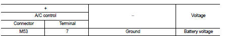
Is the inspection result normal? YES >> GO TO 4.
NO >> Repair harness or connector between A/C control and fuse.
4.CHECK A/C INDICATOR CIRCUIT
Check voltage between A/C control harness connector and ground.
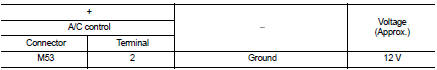
Is the inspection result normal? YES >> GO TO 5.
NO >> Replace A/C control. Refer to HAC-239, "Removal and Installation".
5.CHECK A/C INDICATOR CIRCUIT FOR OPEN
1. Turn ignition switch OFF.
2. Disconnect A/C control connector and BCM connector.
3. Check continuity between A/C control harness connector and BCM harness connecto
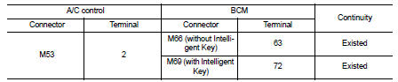
Is the inspection result normal? YES >> Replace BCM. Refer to BCS-93, "Removal and Installation" (with Intelligent Key) or BCS-161, "Removal and Installation" (without Intelligent Key).
NO >> Repair harness or connector.
6.CHECK A/C INDICATOR CIRCUIT FOR SHORT
1. Turn ignition switch OFF.
2. Disconnect A/C control connector and BCM connector.
3. Check continuity between A/C control harness connector and ground.
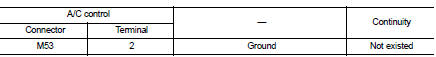
Is the inspection result normal? YES >> Replace BCM. Refer to BCS-93, "Removal and Installation" (with Intelligent Key) or BCS-161, "Removal and Installation" (without Intelligent Key).
NO >> Repair harness or connector
 Thermo control amplifier
Component Function Check
1.CHECK A/C ON SIGNAL
With CONSULT-III
1. Turn ignition switch ON.
2. Select ÔÇťAIR CONDITIONERÔÇŁ of ÔÇťBCMÔÇŁ using CONSULT-III.
3. Select ÔÇťTHERMO AMPÔÇŁ in ÔÇťDATA M ...
 Blower motor
Diagnosis Procedure
1.CHECK SYMPTOM
Check symptom (A or B).
Which symptom is detected?
A >>GO TO 2.
B >>GO TO 7.
2.CHECK FUSE
1. Turn ignition switch OFF.
2. Check 15A fuses ...
Other materials:
Sill cover
Exploded View
1. Screw grommet
2. Screw grommet
3. Sill cover
4. Wind defle
Removal and Installation
REMOVAL
1. Remove sill cover front end fixing screw (A).
2. Remove sill cover rear end fixing screw (A).
3. Remove sill cover lower side fixing screws.
4. Fully open front door and ...
P0340 CMP sensor (phase)
DTC Logic
DTC DETECTION LOGIC
Diagnosis Procedure
1.CHECK GROUND CONNECTIONS
1. Turn ignition switch OFF.
2. Check ground connection E38. Refer to Ground inspection in GI-44, "Circuit
Inspection".
Is the inspection result normal?
YES >> GO TO 2.
NO >> Repair or ...
P0605 ECM
DTC Logic
DTC DETECTION LOGIC
DTC CONFIRMATION PROCEDURE
1.PRECONDITIONING
If DTC Confirmation Procedure has been previously conducted, always turn
ignition switch OFF and wait at
least 10 seconds before conducting the next test.
>> GO TO 2.
2.PERFORM DTC CONFIRMATION PROCEDURE ...
